00198481-01_Technical_Training_E_by_DEK_EN - 第23页
4 Conveyor System 4.3 Overview Conveyor System Electrical System Technical Training E by DEK 12/2017 23 4.3 Overview Conveyor System Electrical System 4.4 Parts Exchange / Settings / Calibrations Conveyor Parts Exchange …
4 Conveyor System
4.2 Conveyor Functionality
22 Technical Training E by DEK 12/2017
NOTICE
Prevent damage to the camera board stop
To prevent damage to the camera board stop, the remote board stop must be used for
product boards over 1kg in weight. Information on the remote board stop is detailed in the
Raising Table chapter of this manual.
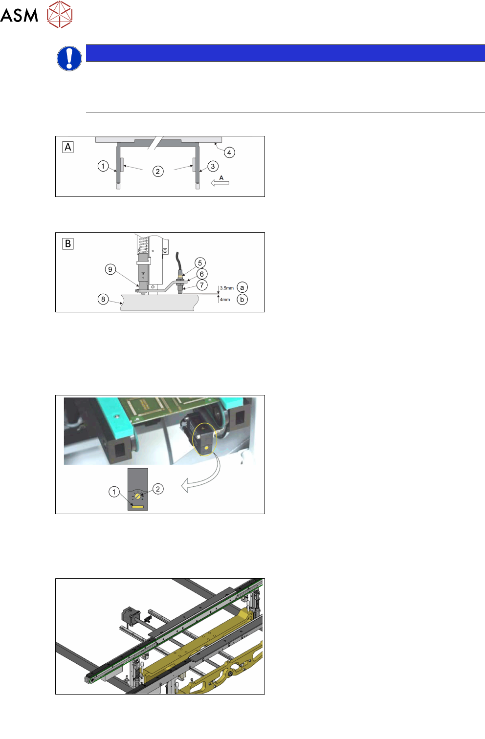
Sensor and Motors
A - Front view of the rail system
1. Left transport leg
2. Linear bearing
3. Right transport leg
4. Rear rail
B - Detailed view on arrow (A picture above)
5. Sensor LED
6. Sensor support bracket
7. Sensor
8. Rail stop bar (Clatter Bar)
9. Shock absorber
a. GO
b. NO GO
The rail lifted sensors are designed as a proximity switch in the current design. These are set as
described above. For detailed information please refer to the reference manual.
1. Test LED
2. SensitivitycControl
The input and output sensors on the transport line are optical sensors. The sensitivity is set on the
potentiometer. If a substrate is detected, the indicator lights up yellow. A blinking indicator is a
weak signal.
The transport system is equipped with one DC motor per rail.
The input and output sensors on the transport line are optical sensors. The sensitivity is set on the
potentiometer. If a substrate is detected, the indicator lights up yellow. A blinking indicator is a
weak signal.
4 Conveyor System
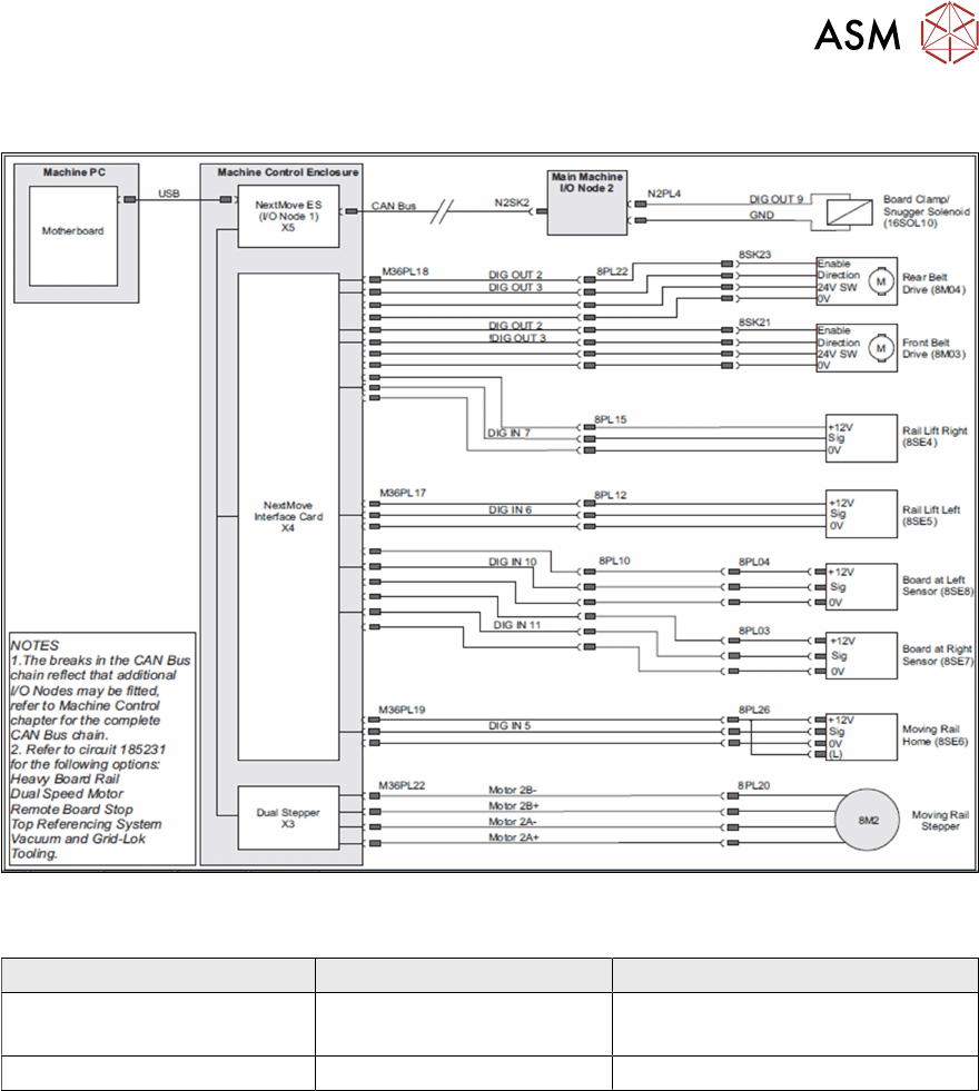
4.3 Overview Conveyor System Electrical System
Technical Training E by DEK 12/2017 23
4.3 Overview Conveyor System Electrical System
4.4 Parts Exchange / Settings / Calibrations
Conveyor Parts Exchange Tools / Setting Calibration
Board Clamp Foil 0.2Nm. screw setting
Board Clamp Setting
Sensor Check / adjust rail width calibration
For detailed instructions refer to the technical reference manual.
4 Conveyor System
4.5 Rising Table
24 Technical Training E by DEK 12/2017
4.5 Rising Table
4.5.1 Main Overview
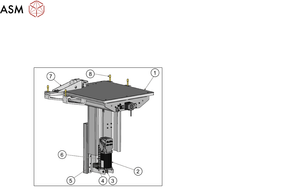
Rising Table Style 2
View on Rear Left of Rising Table Style 2
1. Manual Tooling Plate
2. Rising Table Motor with Integral
Electromagnetic Brake
3. Rising Table drive belt
4. Home Sensor
5. Linear Bearing Guide (in 2 positions)
6. Rising Table Leadscrew
7. Remote Board Stop (Optional)
8. Rail to Table Height Adjuster (in 4
positions)
4.5.2 Rising Table Functionality
The rising table moves up and down within the machine supporting the product board, via the
tooling, and accurately positions the height of the rails at several different pre-determined heights
during the print cycle. The rising table contains the attachment points for the transport rails and the
drive for the moving rear rail, for more information refer to the Transport Rails chapter.
The rising table heights, determined by the software and referenced from the home position, are as
follows:
●
Home position
●
Transport height
●
Vision height
●
Print height
The rising table initializes only once, when the diagnosis is exited or when the machine is switched
on. The transport height is a product-specific setting, which determines the board clearance for
tooling during transport and removal. The vision height puts the substrate in the fixed focus of the
camera. During the alignment sequence, the board remains at the vision height. The rising table
moves in pressure to bring the substrate into contact with the stencil.
The rising table also carries the optional remote on-board stop, which enables heavy substrates to
be transported.