00198481-01_Technical_Training_E_by_DEK_EN - 第32页
5 Gantry Systems 5.1 Print Carriage 32 Technical Training E by DEK 12/2017 5.1.1.1 Reference run / Homing sequence ● During the reference run the system is initialized. The home sensor drives slowly towards the home sens…
5 Gantry Systems
5.1 Print Carriage
Technical Training E by DEK 12/2017 31
5 Gantry Systems
5.1 Print Carriage
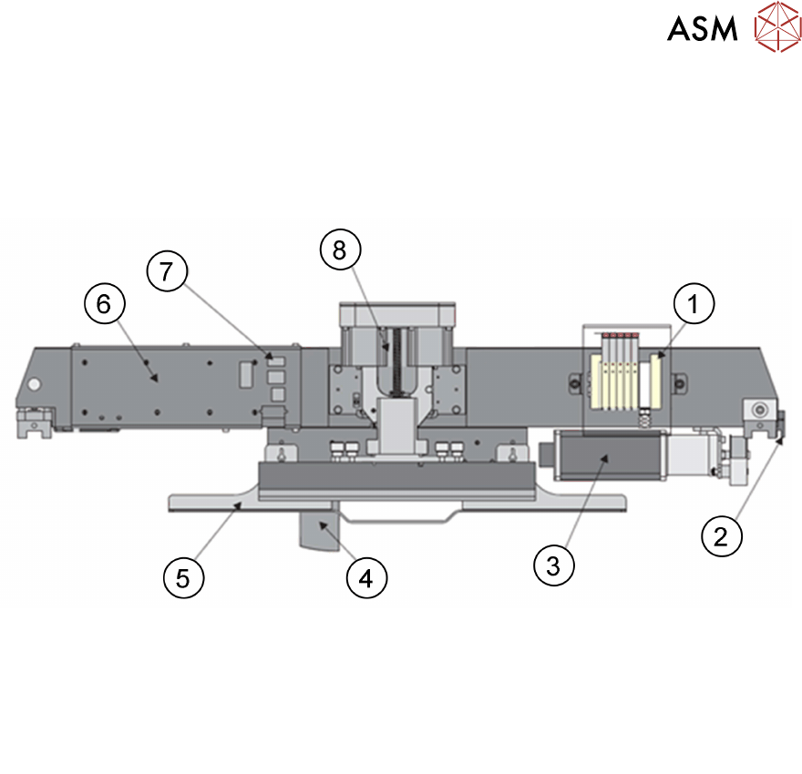
The Print carriage module consists of the following sub-assemblies:
1. Control valve (under metal cover) 6. I/O node board 3 (under metal cover)
2. Home sensor 7. Pressure head connection
3. Print carriage motor (node 7) 8. Squeegee spindle drive
4. Print carriage stencil loader mechanic
5. Paste drip tray
The print carriage module is the vehicle that transports the following:
●
Squeegee
●
Screen Change Module
5.1.1 Print Carriage Functionality
The print carriage allows the following functionality:
●
Print Head Module is able to print any PCB 40.5mm x 50mm up to 508mm x 508mm. (508mm
x 620mm if long board option is enabled). Available Print Head Module is Squeegee
●
Stencil changer for loading and unloading stencils
Reference for each position is the home position which is determined by the home sensor.
The following values are affected:
●
The specific board width
●
Front and rear print limits
●
Front rail setting
During machine initialization the print carriage is referenced. This also happens after leaving the
diagnostic menu.
●
The Node Board 3 is part of the print carriage and includes a temperature and a humidity
sensor.
●
The Node Board 3 also contains an amplifier for the Squeegee pressure feedback.

5 Gantry Systems
5.1 Print Carriage
32 Technical Training E by DEK 12/2017
5.1.1.1 Reference run / Homing sequence
●
During the reference run the system is initialized. The home sensor drives slowly towards the
home sensor vane until the sensor is activated.
●
Then the motor changes direction and moves away from the vane until the sensor is
deactivated
●
The motor stops and the home is reached
1. Home sensor vane
2. Home sensor
5.1.2 Overview Print Carriage Electrical System
5 Gantry Systems
5.1 Print Carriage
Technical Training E by DEK 12/2017 33
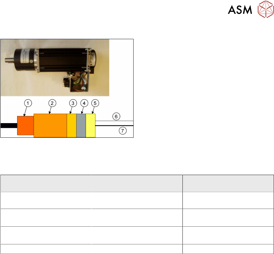
5.1.3 Print Carriage Motor
1. Gearbox
2. Servo motor
3. Drive electronics
4. Processor
5. CAN Open interface
6. CAN bus
7. Power
CAN bus controlled
5.1.4 Parts Exchange / Settings / Calibrations
5.1.4.1 Parts Exchange / Settings / Calibrations
Print Carriage Parts
Exchange
Tools/ Setting Calibration
Node 3 Board Squeegee pressure feedback
calibration
Print Carriage belt Force Meter with hook
12kgs.
Print Carriage Motor Force Meter with hook
12kgs.
Home Sensor / Vane Check Home Position
For the defined measuring position please refer to the technical reference manual