00198481-01_Technical_Training_E_by_DEK_EN - 第36页
5 Gantry Systems 5.1 Print Carriage 36 Technical Training E by DEK 12/2017 5.1.6 Maintenance Maintenance item for print carriage (For details refer to Maintenance Manuals). Maintenance content Interval Requirement Guide …
5 Gantry Systems
5.1 Print Carriage
Technical Training E by DEK 12/2017 35
5.1.5 Analyse Common error list
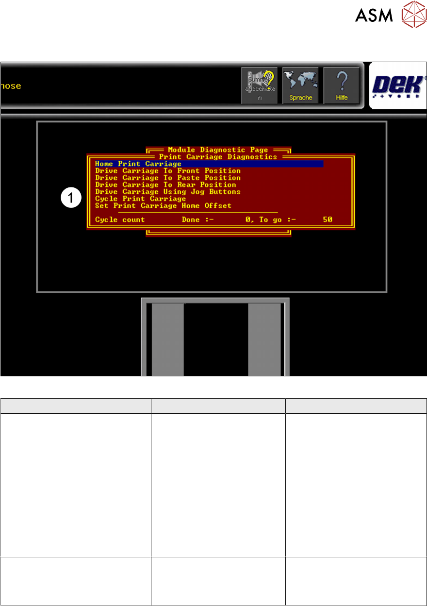
Fig.3: Menu for setting up and calibrating the Print Carriage home positions
Error Description Possible Cause Action
Print Carriage not moving or
jamming
●
Mechanical problem
●
Electrical or control
problem
●
Remove voltages and
check mechanical
movement
●
Check supply voltage,
DEK Power Monitor/
Fuses
●
Check Nextmove ES
Interface Card
●
Check if Motor/Node
defect
●
Check Nextmove Card
Fiducial offset in Y direction when
creating a new product or
importing a product from an other
printer
Play or difficulty with the
Stencil loading
●
Check home position
●
Check Stencil loader
actuators

5 Gantry Systems
5.1 Print Carriage
36 Technical Training E by DEK 12/2017
5.1.6 Maintenance
Maintenance item for print carriage (For details refer to Maintenance Manuals).
Maintenance content Interval Requirement
Guide Rails check and clean Daily IPA wipes
THK AFB grease
Auto drip tray Daily IPA wipes
Spatula
Drag chain and cables for wear 3 monthly
Check Vane position 3 monthly
Cycle carriage to ensure smooth running and belt tracking 3 monthly
Check home position 3 monthly
Check belt tension 3 monthly
5.1.7 Print Carriage - Exercise
Perform the following tasks:
⃞ Check print carriage home position
⃞ Complete preventive maintenance
Describe print carriage theory of operation using module schematic ……………
…………………………………………………………………………………………………
………………………………………………………………………………………………………………
………………………………………………………………………………………………………………
………………………………………………………………………………………………………………
………………………………………………………………………………………………………………
5 Gantry Systems
5.2 Camera System
Technical Training E by DEK 12/2017 37
5.2 Camera System
The camera system consists of the following sub-assemblies:
●
Digital Camera
●
PCI Interface card or Vision card(s) and
vision adaptor card
●
Camera "X" CAN servo motor assembly
(Node 8)
●
Camera "Y" CAN servo motor assembly
(Node 9)
●
X and Y drive belts
●
X and Y through beam opto home sensors
●
Board stop assembly
●
Board at stop reflective opto sensor
5.2.1 Main Overview
5.2.1.1 Camera Module (Rotary Drive)
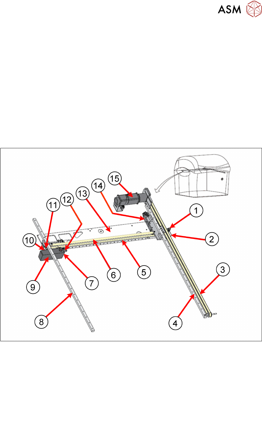
Camera System Overview:
1. Camera Y Home Sensor 9. Camera
2. Camera Y Home flag 10. Camera X Home Flag
3. Camera Y Drive Belt 11. Camera X Home Sensor
4. Camera Y Linear Bearing 12. Board Stop extended Sensor
5. Camera X Linear Bearing 13. Camera axis beam
6. Camera X Drive Belt 14. Camera X Motor (Node 8)
7. Board at Stop Sensor 15. Camera Y Motor (Node 9)
8. Camera Y Linear Bearing