00198481-01_Technical_Training_E_by_DEK_EN - 第69页
8 Communication and Control 8.1 M36 Technical Training E by DEK 12/2017 69 8.1.3 Control Enclosure M36 Module - Next Move Next Move ES Card The Next Move ES can control six stepper motor axes via stepper drive cards. The…
8 Communication and Control
8.1 M36
68 Technical Training E by DEK 12/2017
8.1.2 Control Enclosure M36 Module - Dual Stepper
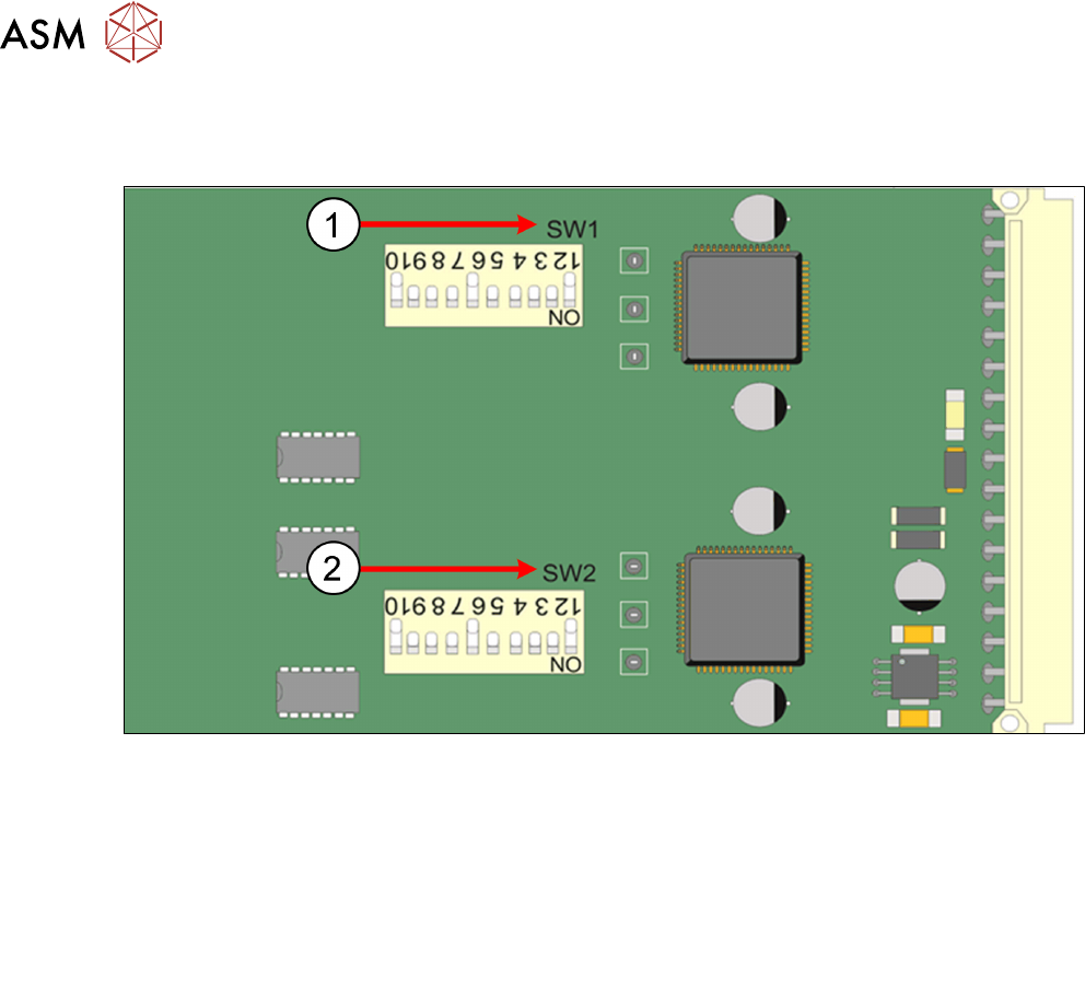
Dual Stepper Drive Card
1. SW1 1 2 3 4 5 6 7 8 9 10
Slots X1 and X3 OFF ON ON ON ON OFF ON OFF ON OFF
Slot X2 OFF ON ON ON ON OFF ON ON ON OFF
2. SW2 1 2 3 4 5 6 7 8 9 10
Slot X1 OFF ON ON ON ON OFF ON OFF ON OFF
Slots X2 and X3 OFF ON ON ON ON OFF ON ON ON OFF
8 Communication and Control
8.1 M36
Technical Training E by DEK 12/2017 69
8.1.3 Control Enclosure M36 Module - Next Move
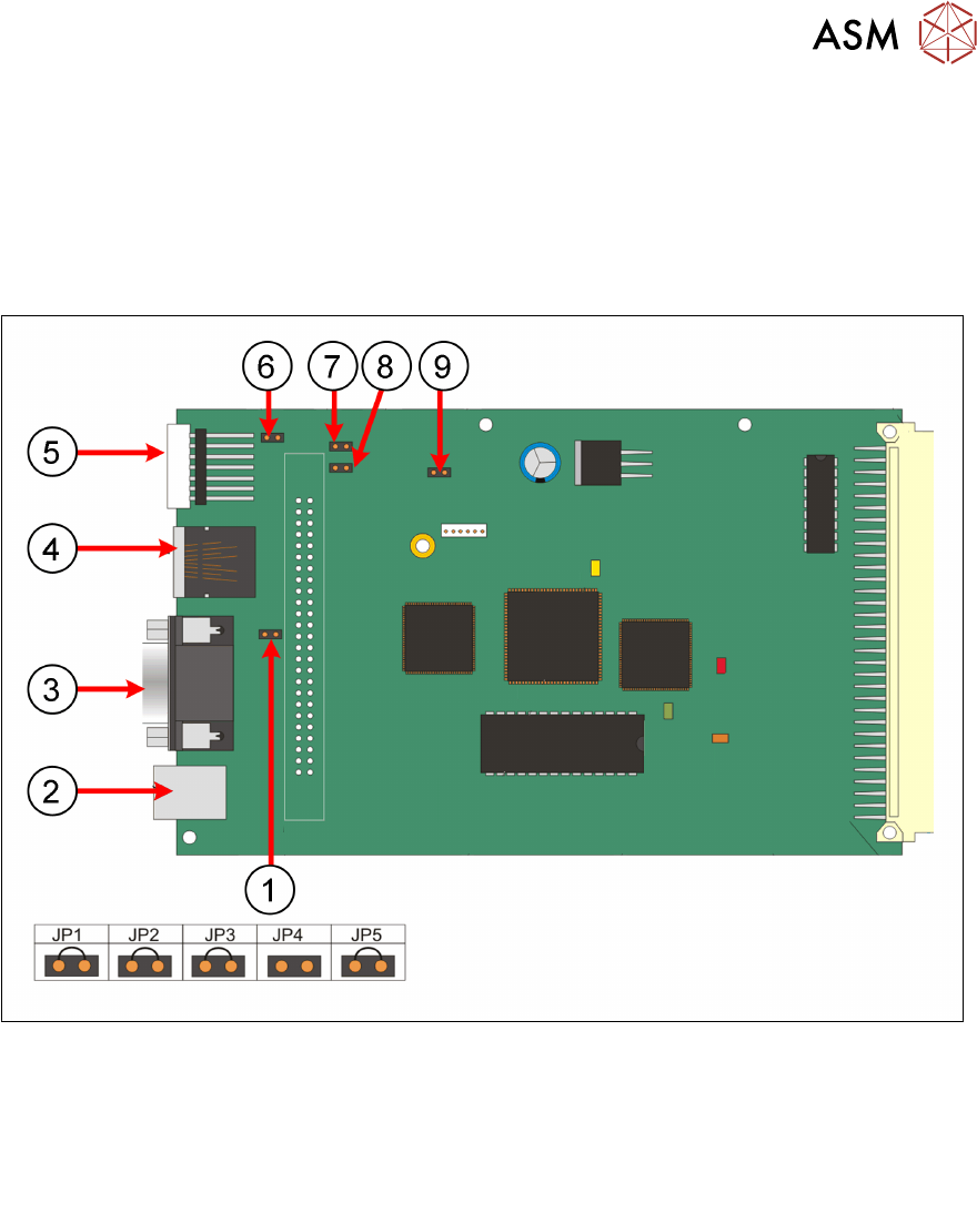
Next Move ES Card
The Next Move ES can control six stepper motor axes via stepper drive cards.
The card also incorporates a CAN encoder/decoder which connects to I/O Node boards and Servo/
Stepper Nodes using a CAN bus network.
When exchanging the card ensure that the correct jumper setting are set.
1. JP2 6. JP1
2. USB connector: M36SK27 7. JP3
3. Not used 8. JP4
4. CAN bus connector: M36SK28 9. JP5
5. 7 Segment: LED display
8 Communication and Control
8.1 M36
70 Technical Training E by DEK 12/2017
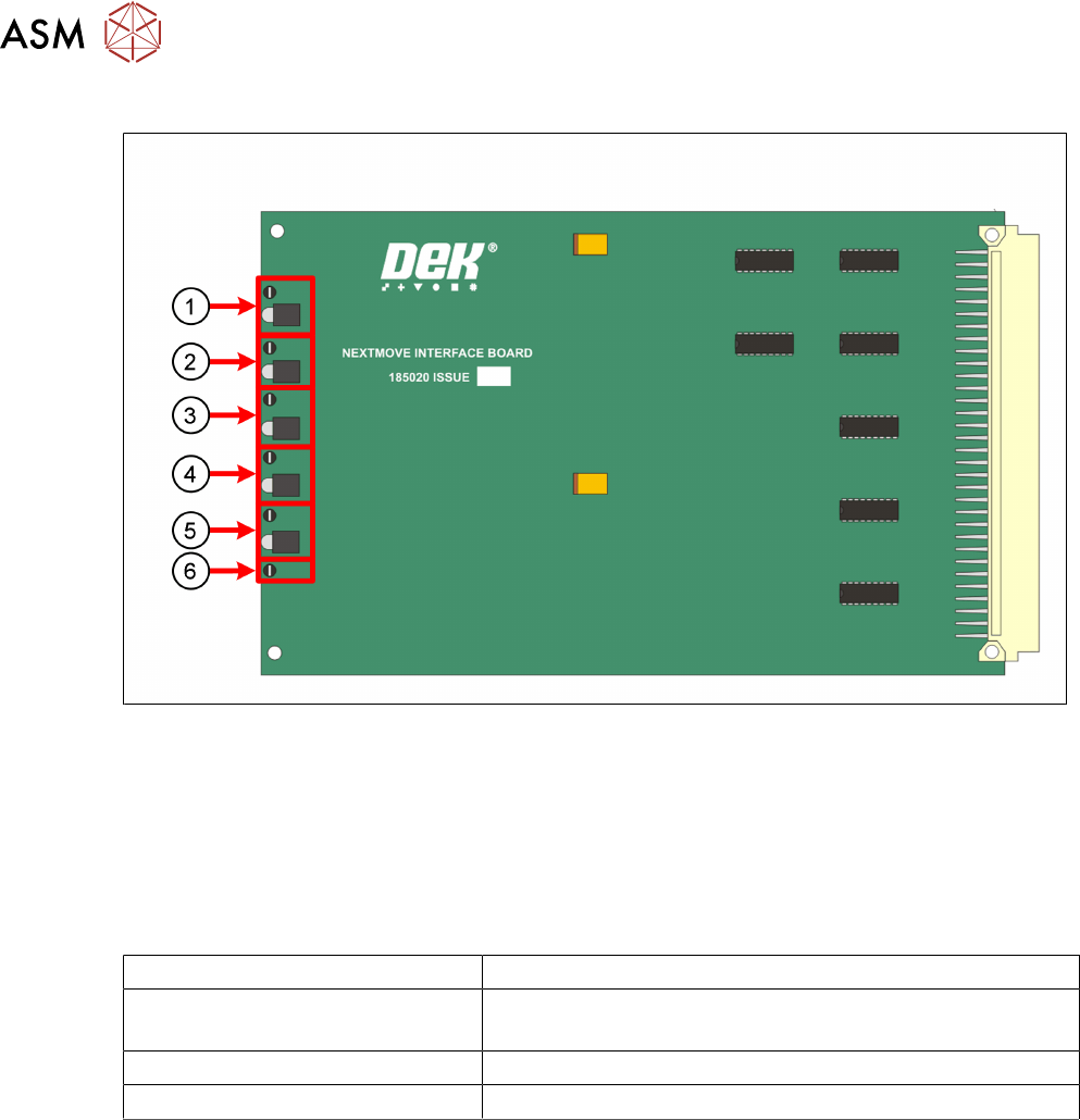
Next Move Interface Card
1. TP 1 + LED 1 = 24V US 4. TP 4 + LED 4 = -12V
2. TP 2 + LED 2 = 24V SW 5. TP 5 + LED 5 = +5.5V
3. TP 3 + LED 3 = +12V 6. TP 6 =DGND
The NextMove Interface Card displays the machine voltages status.
The voltages can be measured at the Test Points.
Next Move ES 7 Segment Display
7 Segment DISPLAY Meaning
- (minus) followed by . (point) If this stays on the display it indicates a 'Fail to Boot'
Possible reasons Corrupt firmware or a low +5.5V
1 Initialized and normal function
E Error missing communication to Machine PC