00198481-01_Technical_Training_E_by_DEK_EN - 第74页
8 Communication and Control 8.4 Analysis Common error list 74 Technical Training E by DEK 12/2017 PC schematic 8.4 Analysis Common error list Error Description Possible Cause Action CAN bus error messages ● Mechanical ● …
8 Communication and Control
8.3 PC Overview
Technical Training E by DEK 12/2017 73
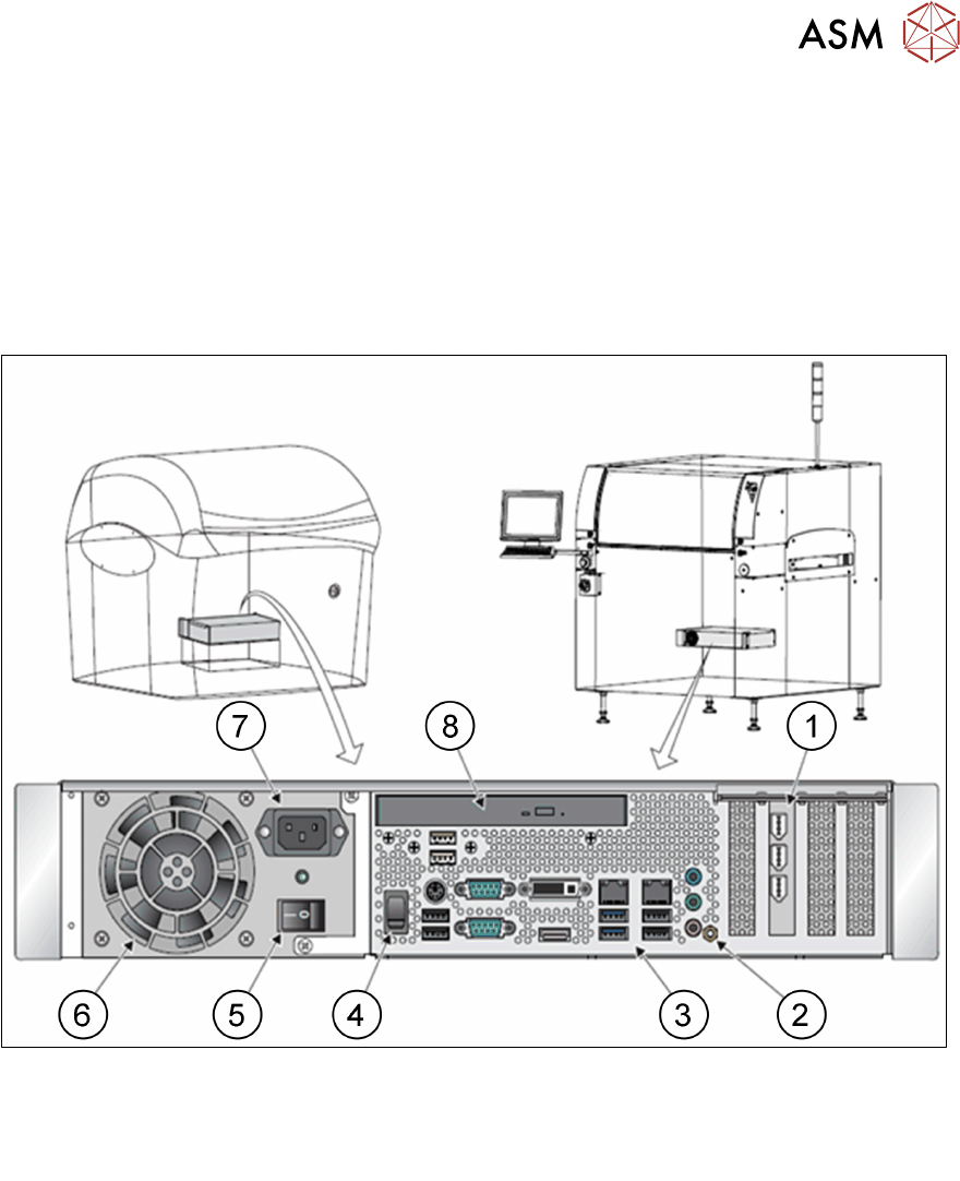
8.3 PC Overview
PC Configuration Summary
The machine PC controls all machine, camera and MMI functions through the CAN bus and local
Host comms.
There are several versions of machine PC depending on machine age.
The current version is H81 PC.
Please check the technical information on the web page for the latest versions.
1.
2.
3.
4.
PC Interface Card
Earth Bonding Connector
Peripheral Connector Panel
Reset Switch
5.
6.
7.
8.
Mains Power On / Off Switch
Cooling Fan
Mains Input Connector
DVD ROM Drive
8 Communication and Control
8.4 Analysis Common error list
74 Technical Training E by DEK 12/2017
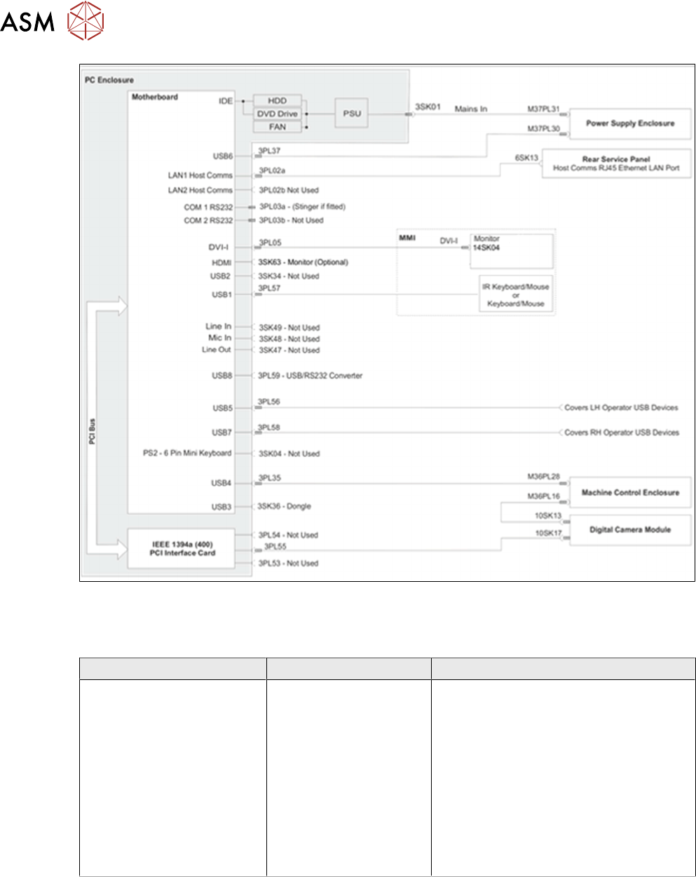
PC schematic
8.4 Analysis Common error list
Error Description Possible Cause Action
CAN bus error messages
●
Mechanical
●
Electrical
●
Look at the Event Log for clues
●
Check CCT breakers
●
Determine which Node is causing
the problem
This can be done using ISCAN*
●
Test CAN bus wire for continuity
and resistance
●
Check Nextmove ES has initialised
OK
●
Check voltages to node(s)
8 Communication and Control
8.5 Exercise
Technical Training E by DEK 12/2017 75
8.5 Exercise
CAN bus
●
Disconnect the CAN bus from the CAN master (Node 1) and measure the line resistance out
(CAN_H to CAN_L):
Ω =
●
Reconnect CAN bus to CAN master, disconnect CAN bus IN from last Node (Node 4 on
Galaxy, Node 8 on Horizon / NeoHorizon) and measure line resistance back to Node 1
(CAN_H to CAN_L):
Ω =
●
With CAN bus connected measure line resistance (CAN_H to CAN_L):
Ω =
●
Measure the resistance from each CAN bus wire to machine chassis GND.
Ω = Ω =
●
Measure CAN bus line resistance:
– With CAN cable connected to Nextmove ES card = 60Ω (2 x 120Ω parallel)
– With CAN cable disconnected from Nextmove ES card or last node
●
Disconnect +24V from a Node and power on machine:
– What message is displayed?
………………………………………………………………………………………………………………
………………………………………………………………………………………………………………
………………………………………………………………………………………………………………
………………………………………………………………………………………………………………
Carry out PCB removal and replacement procedures.
Using the ESD protective equipment supplied and with the aid of the manual, remove one of each
type of card and check for correct configuration. Replace the card ensuring any subsequent
recovery procedures are carried out.
Which configurations and settings must be completed if the Next Move card is changed?
………………………………………………………………………………………………………………
………………………………………………………………………………………………………………
………………………………………………………………………………………………………………
………………………………………………………………………………………………………………
Name 3 locations where +24V can be monitored?
………………………………………………………………………………………………………………
………………………………………………………………………………………………………………
………………………………………………………………………………………………………………
………………………………………………………………………………………………………………
Which cards are interchangeable for troubleshooting purpose?
………………………………………………………………………………………………………………
………………………………………………………………………………………………………………
………………………………………………………………………………………………………………
………………………………………………………………………………………………………………