00198481-01_Technical_Training_E_by_DEK_EN - 第80页
9 Station Software Overview 9.1 Creating a Product file 80 Technical Training E by DEK 12/2017 Fiducial Location It is good practice to choose fiducials that are diametrically opposite and as close to the outer edges as …
9 Station Software Overview
9.1 Creating a Product file
Technical Training E by DEK 12/2017 79
9 Station Software Overview
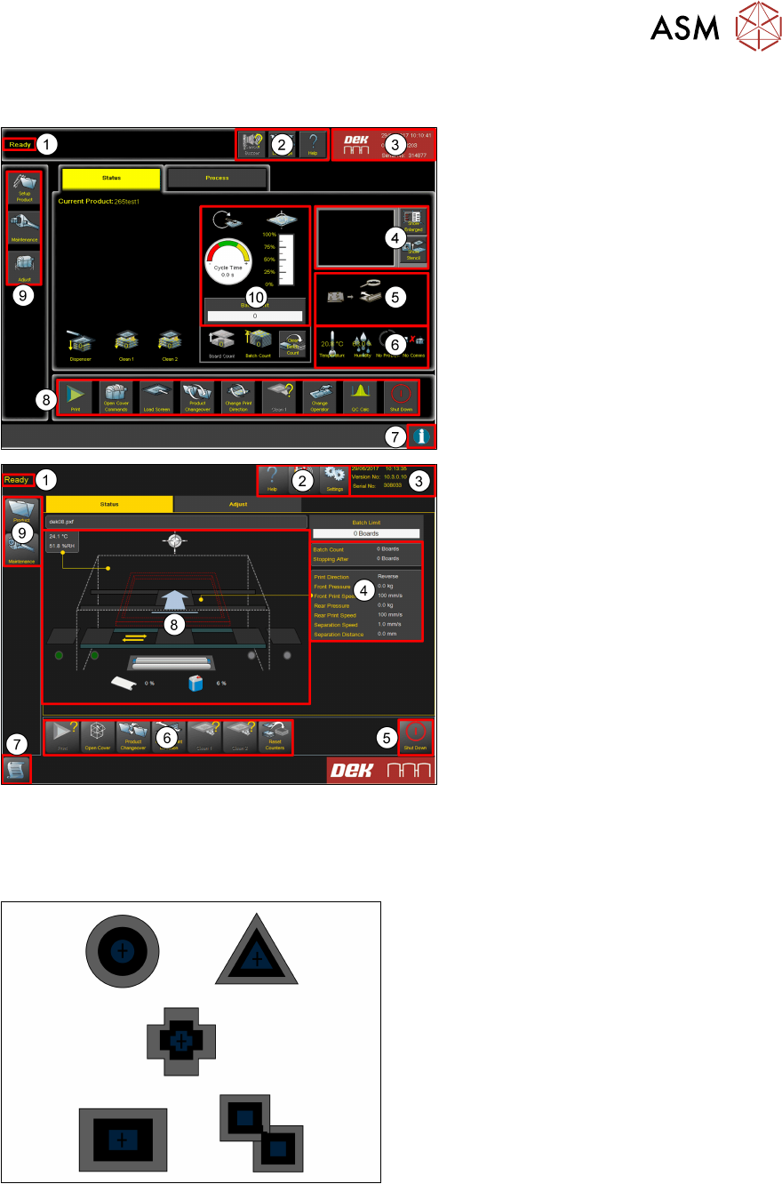
1. Breadcrumb
2. Tools
3. Status
4. Vision window
5. Board Mimic
6. Temperature Humidity Host Comms
7. Information
8. Commands
9. Navigation
10. Performance
1. Breadcrumb
2. Tools
3. Status
4. Detailed machine information
(Process, Transport & USC)
5. Shut down
6. Commands
7. Information
8. Machine mimic
9. Navigation
9.1 Creating a Product file
9.1.1 Setup Synthetic Fiducials
●
Use synthetic fiducials whenever available
●
Diagonally opposite…
●
These must align to corresponding
fiducials on the underside of the stencil.
Failure to set up the fiducials correctly could result in print offsets or vision error messages.
9 Station Software Overview
9.1 Creating a Product file
80 Technical Training E by DEK 12/2017
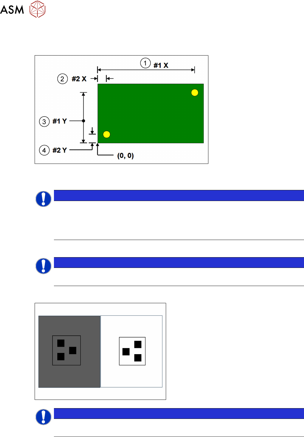
Fiducial Location
It is good practice to choose fiducials that are diametrically opposite and as close to the outer
edges as possible. The following diagram is for a machine set to left fiducial reference:
1. Fiducial #1X 3. Fiducial #1Y
2. Fiducial #2X 4. Fiducial #2Y
NOTICE
Fiducial #1 should be on the right side of the board
Note that Fiducial #1 should be on the right side of the board, to optimize the trajectory of
the camera as it passes from the board stop position to the first fiducial location. It is
possible to program three pairs of fiducials but this is rarely necessary. It may help if the
board is very large, or has many panels and is showing alignment problems
NOTICE
On-board tutorials
Using the on-board tutorials as a guide setup two sets of fiducial.
9.1.2 Setup Video models
●
Unique image
●
Strong contrast
●
Reference to center
●
Strong horizontal & vertical lines
NOTICE
Usage
Used if fiducials poor or damaged and for SPC fault isolation techniques.
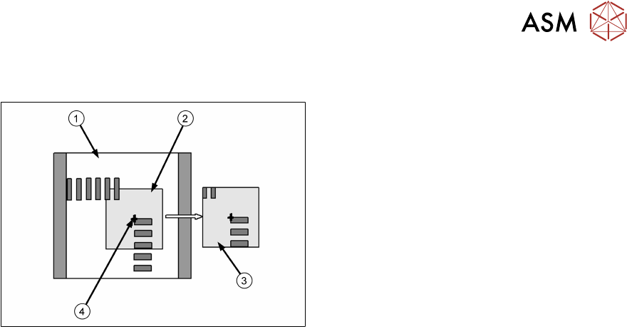
The video model option is useful when there are no synthetic fiducials on the board or stencil, or
when the fiducials are very poor quality. The secret of success is to pick an area of the image that
is unique within the field of view, as shown below.
9 Station Software Overview
9.1 Creating a Product file
Technical Training E by DEK 12/2017 81
The image below is using the corner of a component and, of course, it will have a corresponding
set of apertures on the stencil to align to.
1. Field of view
2. Sample window
3. Learned model
4. Alignment point
Problems and Limitations
Video models should never be considered as a first choice for alignment as there are several
disadvantages:
●
Due to the normal practice of using aperture reduction, the alignment point of the stencil video
model is unlikely to match that of the board. Therefore, the need to program print offsets is
common when using video models.
●
The stencil capture score may deteriorate rapidly once the stencil is contaminated with paste.
Therefore, it is necessary to use the under-screen cleaner more often than is desirable,
sometimes after every print!
●
On a heavily populated board it is often difficult to find an area that contains a unique image.
The software may detect multiple possible targets within the field of view. If this happens it
may help to increase the Accept Score so that only the true video model will be captured.
Exercise
●
Create a new board file based giving it the name "Video" and ID "video model practice".
●
Setup two sets of video models.