00198481-01_Technical_Training_E_by_DEK_EN - 第88页
10 Machine Modules 10.1 Stencil Mount 88 Technical Training E by DEK 12/2017 10.1.3 Adjustable Width Screen Mount (AWSM) Module 1. Width Locking Mechanism (Rear) 10. Chase Rail Assembly guide shaft (Front) 2. Chase Rail …
10 Machine Modules
10.1 Stencil Mount
Technical Training E by DEK 12/2017 87
10.1.2.1 C-Chase Functionality
●
The C-chase only supports stencil widths of 736mm without any adaptation of the stencil.
●
The stencil is loaded from the front and is placed on stencil supports. Spring plates on the
right side push the stencil to the left edge of chase. Once loaded the Stencil is held in
positioned by 6 pneumatic clamps.
●
The clamp pressure is adjustable.
●
The chase is a floating assembly mounted on 4 roller plates.
●
The chase is positioned to align the screen to the correct printing position.
●
During the print cycle the complete chase is positioned and help in place by 2 diagonally
positioned pneumatic cylinders.
●
A sensor in the sensor of the unit recognizes the stencil presence.
●
There are 3 methods to load the stencil:
– Screen depth Adjuster
– Semi auto stencil Loader
– Auto stencil Loader
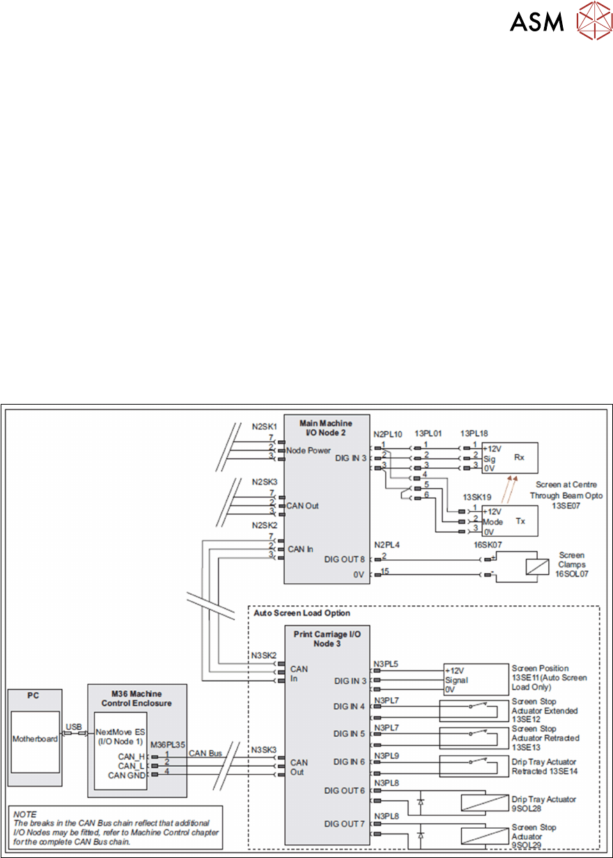
10.1.2.2 C_Chase Electrical Overview
10 Machine Modules
10.1 Stencil Mount
88 Technical Training E by DEK 12/2017
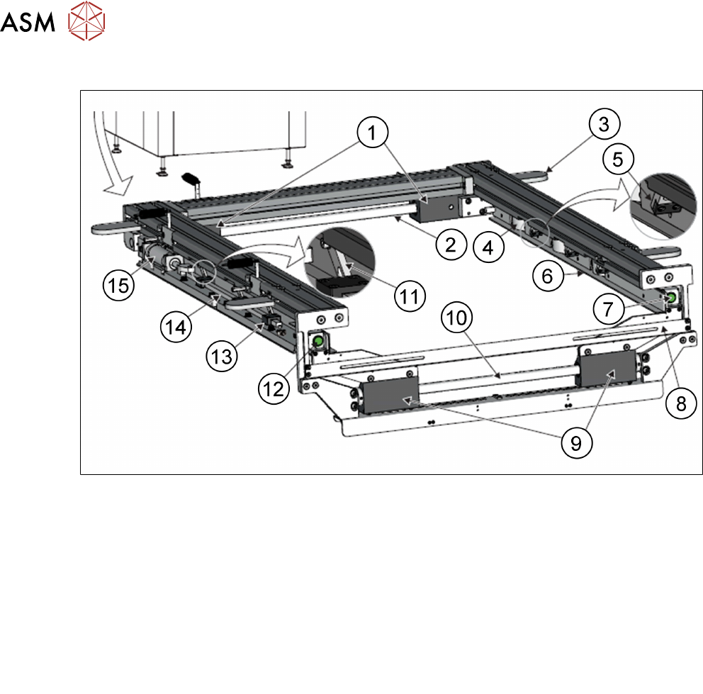
10.1.3 Adjustable Width Screen Mount (AWSM) Module
1. Width Locking Mechanism (Rear) 10. Chase Rail Assembly guide shaft (Front)
2. Chase Rail Assembly guide shaft (Rear) 11. Stencil Clamp Lever (6 positions)
3. Roller Count Plate (4 positions) 12. Left Hand Chase Release Button
4. Stencil Location Leaf Spring(3 positions) 13. Stencil Clamp Lever Actuator Bar Guide
(6 positions)
5. Screen Clamp Assembly (6 positions)
6. Stencil Support Plate (2 positions) 14. Stencil Clamp Lever Actuator Bar
(2 positions)
7. Right Hand Chase Release Button
8. Screen Width Measuring Scale 15. Stencil Clamp Pneumatic Cylinder
(2 positions)
9. Width Locking Mechanism (Front)
10 Machine Modules
10.1 Stencil Mount
Technical Training E by DEK 12/2017 89
10.1.3.1 AWSM Functionality
The module width can be easily adjusted by an operator to accommodate different stencil sizes
and has permanent markings for standard stencil sizes.
●
Fully adjustable to accommodate stencil sizes in the range of 381mm to 736mm (15 inches to
29 inches).
●
The height of the stencil must exceed 19mm to be clamped firmly.
●
The stencil image can be either centered edge positioned or customized.
●
Pneumatic push buttons located on the front of the left and right hand chase rail assemblies
are operated, releasing all four locks on the front and rear chase rail assembly guide shafts.
Releasing the chase rail assemblies allows the user to adjust the position of the left and right
hand chase rail assemblies, to accommodate for the appropriate size stencil using the stencil
width measuring scale.
The stencil is loaded from the front and is placed on stencil supports. Spring plates on the right side
push the stencil tot he left edge of ASM. Once loaded the Stencil is held in positioned by 8 clamps.
●
The clamp pressure is adjustable.
●
The ASM is a floating assembly mounted on 4 roller plates. During the print cycle the
complete chase is positioned and help in place by 2 diagonally positioned pneumatic
cylinders.
●
A sensor in the sensor of the unit recognizes the stencil presence.
There are 2 methods to load the stencil:
●
Auto stencil Loader The auto screen loader (ASL) accurately positions the stencil/screen in
the chase. The ASL is incorporated into the squeegee drip tray mechanism which is secured
beneath the print carriage, therefore the drive is provided by the print carriage drive system.
●
Semi Auto stencil Loader The semi-auto screen loader (S-ASL) positions the stencil after
the operator has placed it in the chase. The screen loader mechanism is incorporated into the
squeegee drip tray mechanism which is secured beneath the print carriage, therefore the
drive is provided by the print carriage drive system.
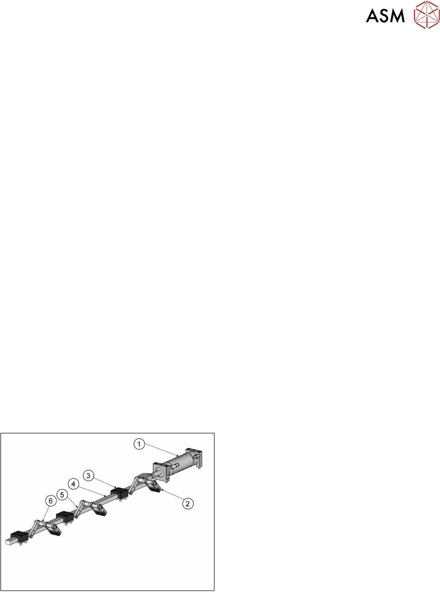
Stencil Clamping
1. Stencil clamp pneumatic cylinder
2. Stencil clamp
3. Stencil clamp lever actuator bar guide
4. Stencil clamp lever actuator bar
5. Stencil clamp lever
6. Pivot point
To clamp the stencil in the AWSM, the stencil clamp pneumatic cylinder is extended pushing the
lever actuator bar towards the front of the machine. This operates the clamp levers which pivots the
stencil clamps downwards applying pressure on the top of the stencil frame