00198481-01_Technical_Training_E_by_DEK_EN - 第94页
10 Machine Modules 10.1 Stencil Mount 94 Technical Training E by DEK 12/2017 10.1.4.2 Screen Alignment Analyses Error Description Possible Cause Action Alignment close to limits (XF+XR) > +/-14mm i.e. XF=8, XR = 7 Add…
10 Machine Modules
10.1 Stencil Mount
Technical Training E by DEK 12/2017 93
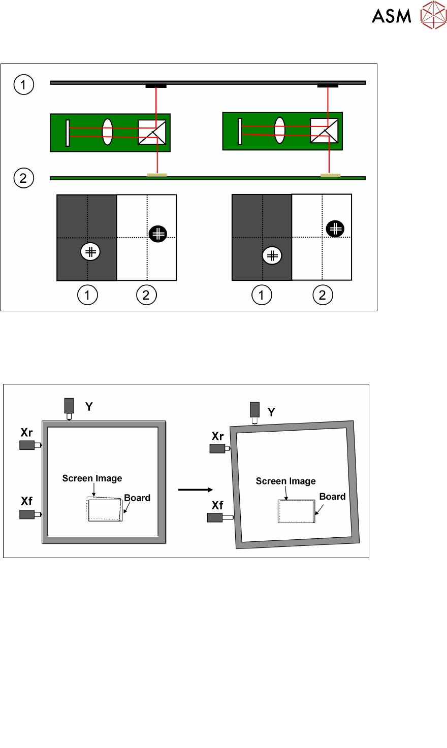
10.1.4.1 Screen Alignment Functionality
1.Stencil 2.Board
The camera captures each of the fiducials (screen and board) and sends the data to the processor.
The processor uses this data as well as the calibration data to calculate the amount of stencil
movement required to align the stencil to the board. The processor then tells the actuators to move
the print stencil in the X, Y and theta direction.
.
Limits of travel : Xf, Xr = ±9mm approx. Y = ±9mm approx.
Offsets : Y = ± 1mm X = ±1mm, theta ±1000aSec
The alignment system consists of three stepper motor driven linear actuators in contact with the
chase (adjustable stencil mount)
The actuators are configured in a three point contact arrangement and are controlled and driven
independently to give maximum flexibility in stencil movement.
The actual distance moved by the actuators will be determined by:
●
Distance between board and stencil
●
Camera scale and offset calibration factors
●
Applied offsets
●
Alignment weighting
●
Pitch of actuator lead screw
●
Step configuration of drive card
●
Smallest moveable distance
– 3.41 microns currently
– 0.4 microns with micro-step introduction
10 Machine Modules
10.1 Stencil Mount
94 Technical Training E by DEK 12/2017
10.1.4.2 Screen Alignment Analyses
Error Description Possible Cause Action
Alignment close to
limits
(XF+XR) > +/-14mm
i.e. XF=8, XR = 7
Add / subtract 7.5 to board stop X dimension (but
remember squeegees and dedicated tooling can-
not be moved from centre!)
Alignment close to
limits
(XF-XR) > +/-7mm
i.e. XF=5, XR = -3
1. Check image position on screen.
2. Check rail width (excess skew)
3. Check fiducials (other similar looking fiducial
in field of view?)
4. Check Actuator Springs
5. Check Print Carriage home position
6. Check Print carriage belt tracking
7. Use "Customise Screen" option
Alignment close to
limits
Y > +/- 7 mm
i.e. Y=8
Alignment Out of
Range
(XF+XR) > +/-18mm
i.e. XF=-9, XR = -9.5
Subtract 9.25 from board stop X
Dimension (but remember squeegees and
dedicated tooling cannot be moved from centre!)
Alignment Out of
Range
(XF-XR) > +/-9mm
i.e. XF=-6, XR =3.5
1, 2, 3 and 4 above
Alignment Out of
Range
Y > +/- 9 mm
i.e. Y=9.5
1, 2, 3, 4, 5, 6 and 7 above
In General check the following critical areas of the alignment system:
●
Chase clamp gap
●
Chase clamp friction during alignment
●
Grooves in roller counter plates
●
Damaged actuators
●
Broken stepper motor
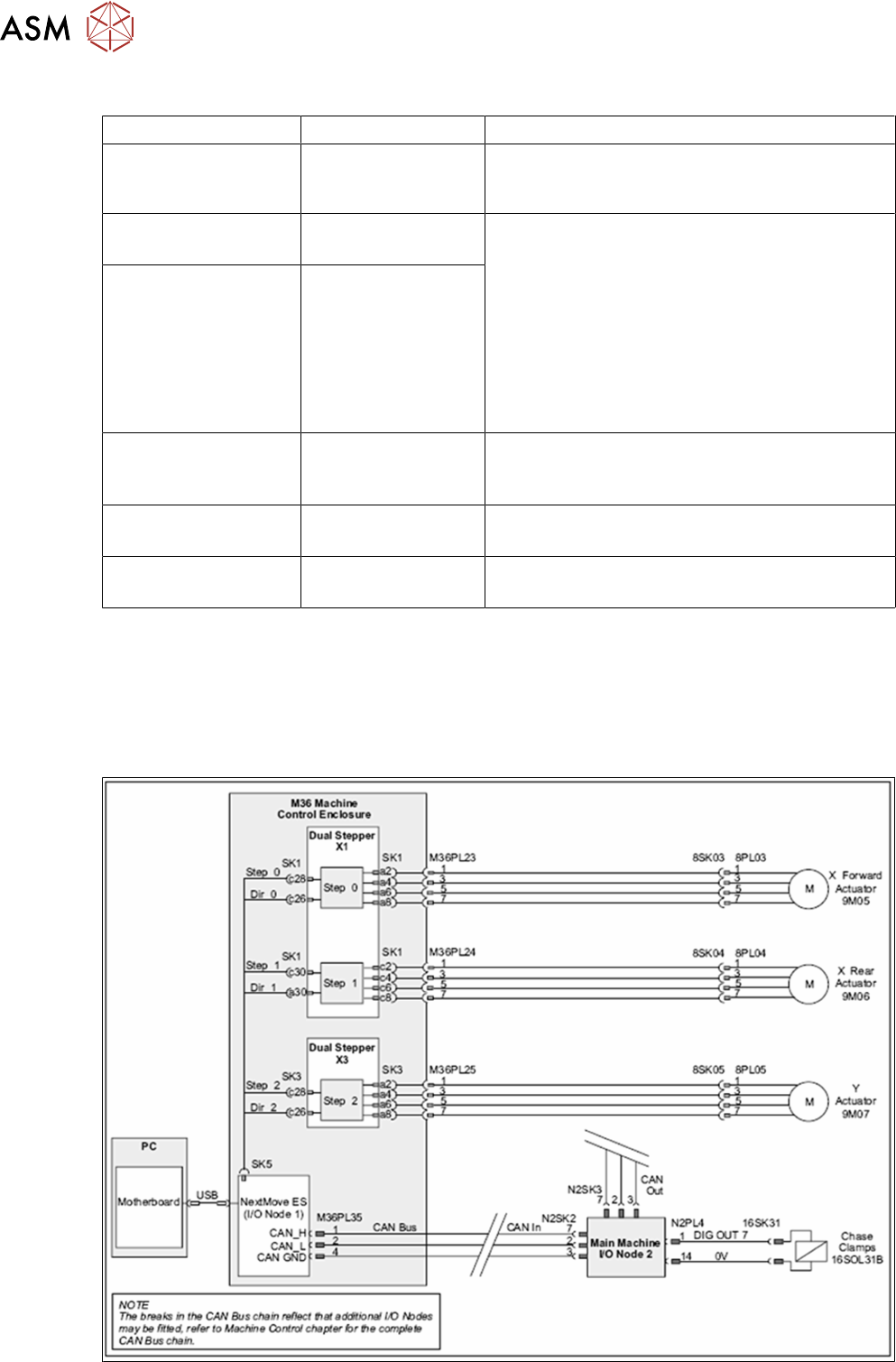
10.1.4.3 Screen Alignment Module - Electrical Overview
10 Machine Modules
10.1 Stencil Mount
Technical Training E by DEK 12/2017 95
10.1.4.4 Screen Alignment Module - Exercise
Maintain the Screen Alignment System
Perform the following tasks:
⃞ Remove and replace an actuator
⃞ Remove and replace a chase clamp
⃞ Check roller counter plates for wear
⃞ Adjust chase clamp air gap
⃞ Adjust chase clamp air pressure and measure clamp strength
⃞ Describe screen alignment theory of operation using module schematic
10.1.5 Parts Exchange / Settings / Calibrations
Parts Exchange Tools / Setting Calibration
Actuator Standard tools Vision and Offset Calibration
Roller Bearing Counter late Standard tools None
Roller Bearing Standard tools Coplanarity (Chase to Table Height)
For detailed instructions refer to the technical reference manual.
10.1.6 Analysis Common error list
Problems Solution
Fiducial not found, poor SPC,
poor print alignment
Swap X with Y actuators and retest.
Poor alignment
●
Check for grooves worn in the counter plate.
●
Replace plate.
Poor alignment
●
Check the roller bearing is free.
●
Lubricate or replace.
For detailed instructions refer to the technical reference manual.
10.1.7 Maintenance
Maintenance item for Conveyor system.
Maintenance content Interval Requirement
Roller bearing and counter plate Annual Check for groove in hardened pad.
Roller bearing and counter plate Annual Lubricate with light machine oil (ensure no
lubrication on top surface of counter plate).
Actuator roller end and striker plate Annual Clean and lubricate with light machine grease.
For detailed instructions refer to the technical reference manual.