晶圆测试说明书Cascade-11861-6-Manual.pdf - 第48页
24 • Summit 11K/12K Probe Station User’ s Guide 11800 G UARDED T HERMAL P RO B E S TATIONS The 11800 offers the same thermal testing capacity as an 11700, but with an advanced reduced-noise th ermal chuck. Using Cascade …
Chapter 2: Station Specifications •
23
11700 GUARDED THERMAL PROBE STATIONS
The 11700 offers the same thermal testing capacity as a 11600, but with an
advanced reduced-noise thermal chuck. Using Cascade Microtech’s patented
FemtoGuard thermal chuck technology, the 12700 provides wafer temperature
control in a reduced noise and capacitance environment. Chuck noise is reduced
1000-times over standard thermal chucks. The noise on topside probes reduces to
fA levels.
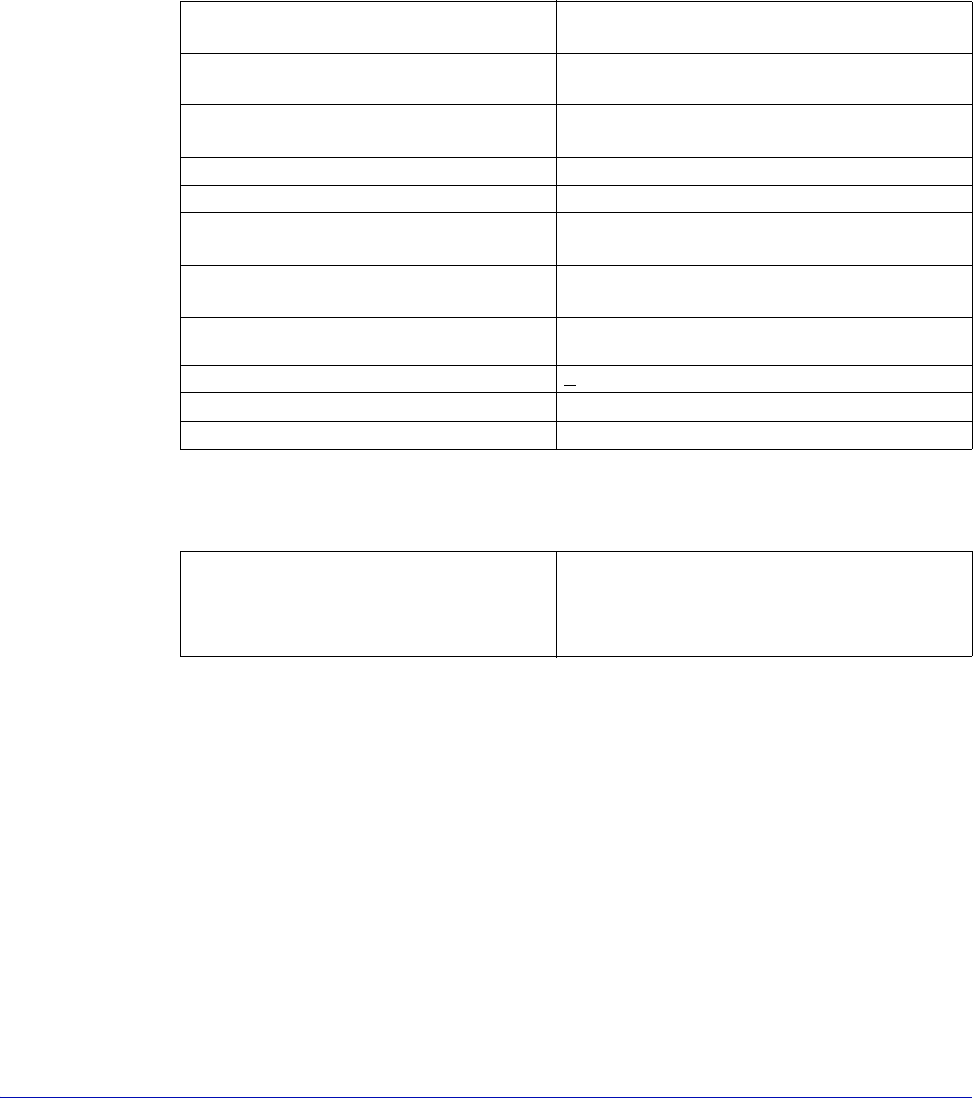
Chuck Specifications
Total System Planarity
Planarity includes all error sources.
Flatness 25-micron (1 mil) to 130 °C, 51 micron (2
mil) to 200 °C
Residual capacitance, chuck to
shield
< 50 pF
Capacitance variation over chuck
surface
≤ 30 fF
Isolation, chuck to shield > 1 TΩ
Breakdown bias voltage > 500-volts
Chuck leakage current, thermal
chuck on
0 to 100-volts: < 50 fF
Chuck leakage current, thermal
chuck off
0 to 100-volts, 20 fF
Temperature range
-65 °C to 200 °C maximum (controller
dependent). 300
o
C on HT version.
Temperature uniformity +0.5 °C or 0.5% whichever is higher
Vacuum distribution area 13, 75, or 152 mm (selectable)
Auxiliary chucks Two with individual vacuum control
Total system planarity <30-micron (1.2 mil) across 101 mm
(4 in.) circle
<40-micron (1.6 mil) across 203 mm
(8 in.) circle
24
• Summit 11K/12K Probe Station User’s Guide
11800 GUARDED THERMAL PROBE STATIONS
The 11800 offers the same thermal testing capacity as an 11700, but with an
advanced reduced-noise thermal chuck. Using Cascade Microtech’s patented
FemtoGuard thermal chuck technology, the 12700 provides wafer temperature
control in a reduced noise and capacitance environment. Chuck noise is reduced
1000-times over standard thermal chucks. The noise on topside probes reduces to
fA levels.
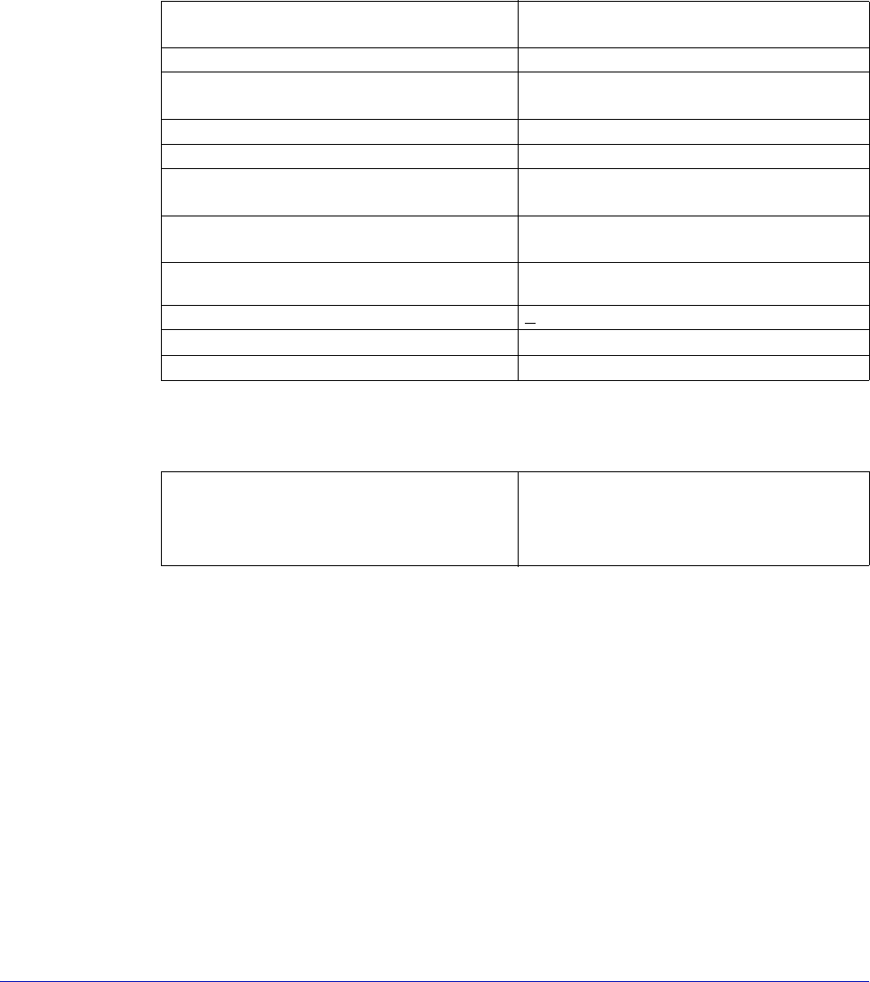
Chuck Specifications
Total System Planarity
Planarity includes all error sources.
Flatness 25-micron (1 mil) to 130°C, 51-micron
(2 mil) to 200°C
Residual capacitance, chuck to shield 1 pF
Capacitance variation over chuck
surface
3 fF
Isolation, chuck to shield > 1 TΩ
Breakdown bias voltage > 500-volts
Chuck leakage current, thermal
chuck on
0 to100-volts: < 50 fA
Chuck leakage current, thermal
chuck off
0 to100-volts, 20 fA
Temperature range
-65 °C to 200 °C maximum (controller
dependent). 300°C on HT version.
Temperature uniformity +0.5 °C or 0.5% whichever is higher
Vacuum distribution area 13, 75, or 152 mm (selectable)
Auxiliary chucks Two with individual vacuum control
Total system planarity <30-micron (1.2 mil) across 101 mm
(4 inch) circle
<40-micron (1.6 mil) across 203 mm
(8 inch) circle
Chapter 3: Installing •
25
CHAPTER
3
Installing Chapter 5
Before Installing
Verify that your work area conforms to the site specifications described in the
Station Overview chapter.
LIFTING REQUIREMENTS
You will need:
• Four or five people to maneuver the probe station onto the table
• Forklift with a minimum 272 kg (600 lb.) capacity
TOOLS NEEDED
You supply a 9/16-in., open-end or socket wrench to remove the bolts on the
shipping crate. We supply a set of hex wrenches for probe station screws.
Installation Overview
Install your probe station using the procedures in this chapter.
You should also refer to this procedure if you are removing your probe station.
WARNING
Several probe station components weigh 23 kg (50 lb) or more; the probe station
weighs over 136 kg (300 lb). To prevent physical injury, refer to and follow lifting
guidelines provided by your company.
Note that this installation procedure may have instructions for station models
with different options.
• Sections may describe generic procedures that apply to all stations
• Sections that apply to a specific model number or option are so labeled