晶圆测试说明书Cascade-11861-6-Manual.pdf - 第64页
40 • Summit 11K/12K Probe Station User’ s Guide a Available only in the U.S. and Japan. C ONNECT THE C HUCK V ACUUM H OSE (11000-Series Only) T o connect the chuck vacuum hose 1. Connect a 1/8-inch diameter h ose to the …
Chapter 3: Installing •
39
INSTALL THE COMPUTER AND HOSES
(12000-Series Only)
To install the computer, cables, and hoses
1. Unpack the computer, the keyboard, the joystick, the mouse, the cables, and
the video monitor.
2. Seat the computer under your workbench, and place the keyboard, monitor,
joystick and mouse on the workbench next to the station.
3. Connect the “keyed” cables and hoses as described in Table 1. See also, figure
29 on p. 41.
Table 1. 12000-family probe station cables and hoses.
Cable or Hose From To
main control cable computer connector on
the back side of the
probe station
computer
monitor extender cable monitor connector on
computer
monitor cable
keyboard cable keyboard computer PS2 port
mouse cable mouse computer PS2 port
air line (high-stability
bridge only)
Air in (left rear of station) compressor or air supply
joystick cable joystick computer
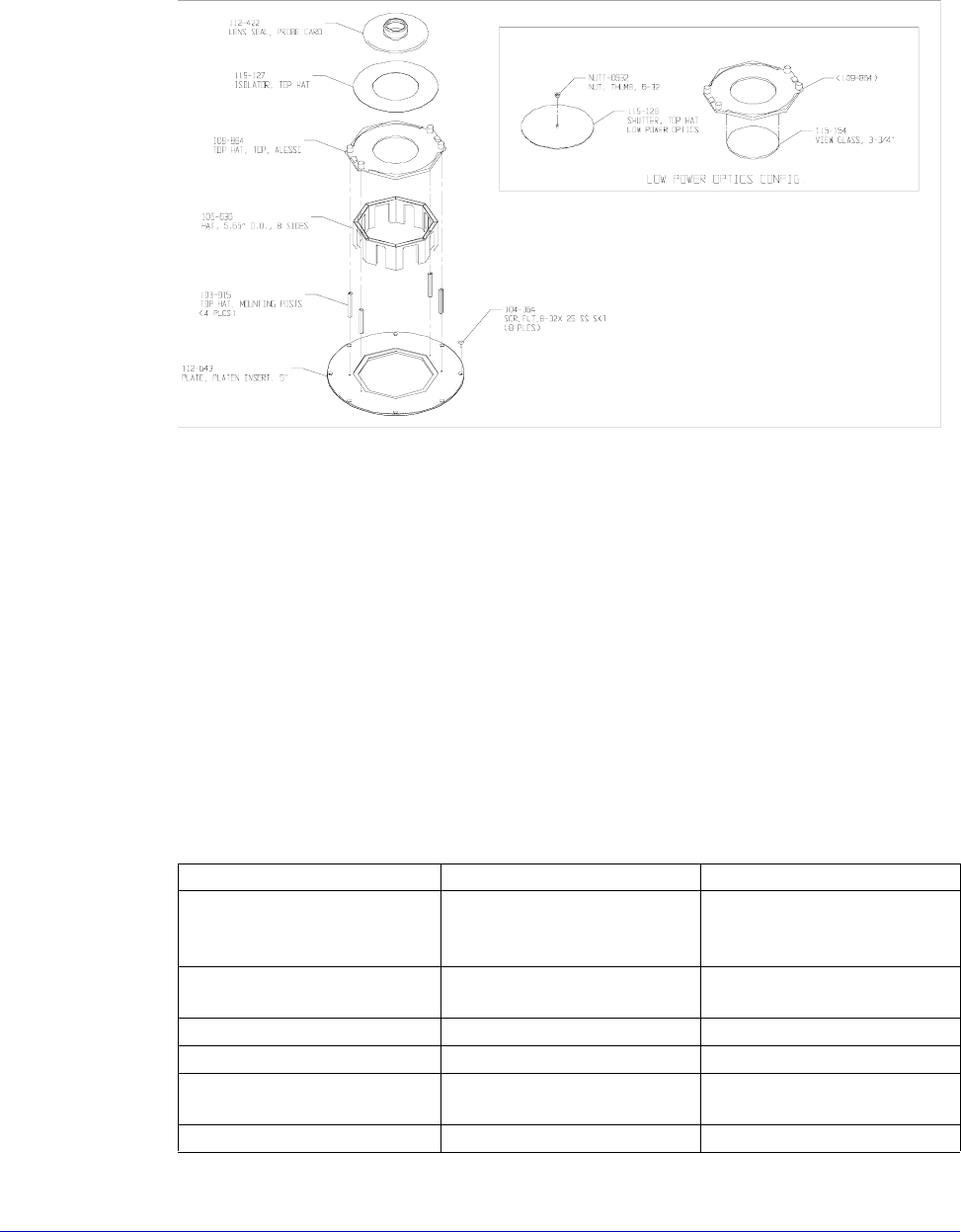
Fig. 28. Microscope TopHat seal (left) for Mitutoyo, Optem and Olympus.
40
• Summit 11K/12K Probe Station User’s Guide
a
Available only in the U.S. and Japan.
CONNECT THE CHUCK VACUUM HOSE
(11000-Series Only)
To connect the chuck vacuum hose
1. Connect a 1/8-inch diameter hose to the vacuum input on the back of the
probe station. See figure 29 on p. 41.
2. Connect the other hose end to your vacuum source.
3. Connect a 1/8-inch diameter hose to the vacuum input on the back of the rear
connection panel (if ordered). See figure 29 on p. 41.
4. Connect the other hose end to your vacuum source--use a 3-way tee to
connect both vacuum inputs using one vacuum source.
power cable probe station wall outlet
Cable or Hose From To
power cable monitor wall outlet
power cable computer wall outlet
extension power cable
a
(optional)
MICROSCOPE POWER on
probe station
extension power cable
a
(optional)
AUXILIARY POWER on
probe station
black vacuum hose
(for chuck vacuum)
VAC IN on probe station
(Right side of the probe
station.)
optional vacuum pump
-or-
your vacuum source
black vacuum hose (for
vacuum-mounted
positioners). Use 1/8 inch
3-way tee between probe
station and connection
panel.
VAC I N on r e a r
connection panel (if
ordered)
optional vacuum pump
-or-
your vacuum source
Quadrax, BNC, Triax, or
Dual Triax Cable
(HP4142 or HP4145 only)
See Fig. 4-32.
Table 1. 12000-family probe station cables and hoses.
Chapter 3: Installing •
41
To add counterbalance weights
(Large-area bridge mount only)
Each large-area bridge mount is configured to a system at the factory so that the
counterbalance is already adjusted. If the bridge mount is a retrofit, the
counterbalance must be adjusted.
• If you add an option, such as a camera, you may need to add extra weight to
the microscope counterbalance.
• If you add an Olympus Stereo-Zoom Microscope, you may be required to
remove the weights.
• Some applications (i.e., one using a MicroChamber and only one or two
objectives) may require the removal of a small amount of weight.
The probing station includes two counterbalance weights with the hardware and
other parts shipped. You can add a total of two weights to each side of the
counterbalance.
To add weight to the counterbalance
1. Remove the back cover of the optics bridge, as described in the section To
Remove the Optics Bridge Mount Shipping Restraints. See figure 17 on p. 31.
2. Add one or two weights to the counterbalance, as shown in figure 30. The
weights are shaped so that they can be installed in only one orientation.
3. Replace the back cover of the optics bridge.
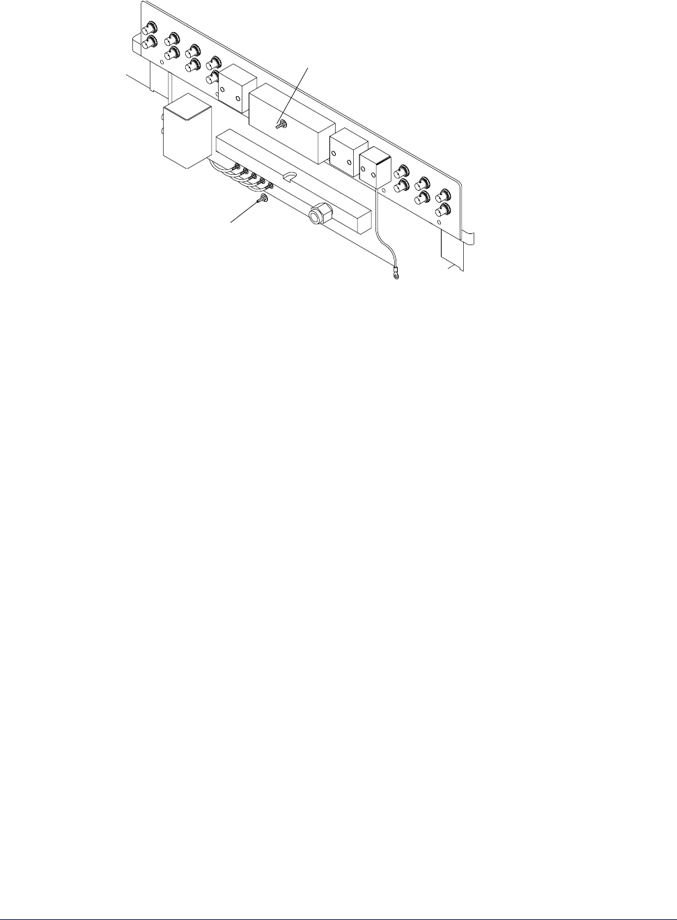
Fig. 29. Vacuum hose connection.
Vacuum input
Probe Station
Rear Connection Panel (if ordered)
Vacuum input