晶圆测试说明书Cascade-11861-6-Manual.pdf - 第67页
Chapter 3: Installing • 43 • If the indicator’s reading was positive, adjust the front sets crews on both sides a thousandth of an inch past zero. • If the indicator’s reading wa s neg ative, adjust the back setscrew s o…
42
• Summit 11K/12K Probe Station User’s Guide
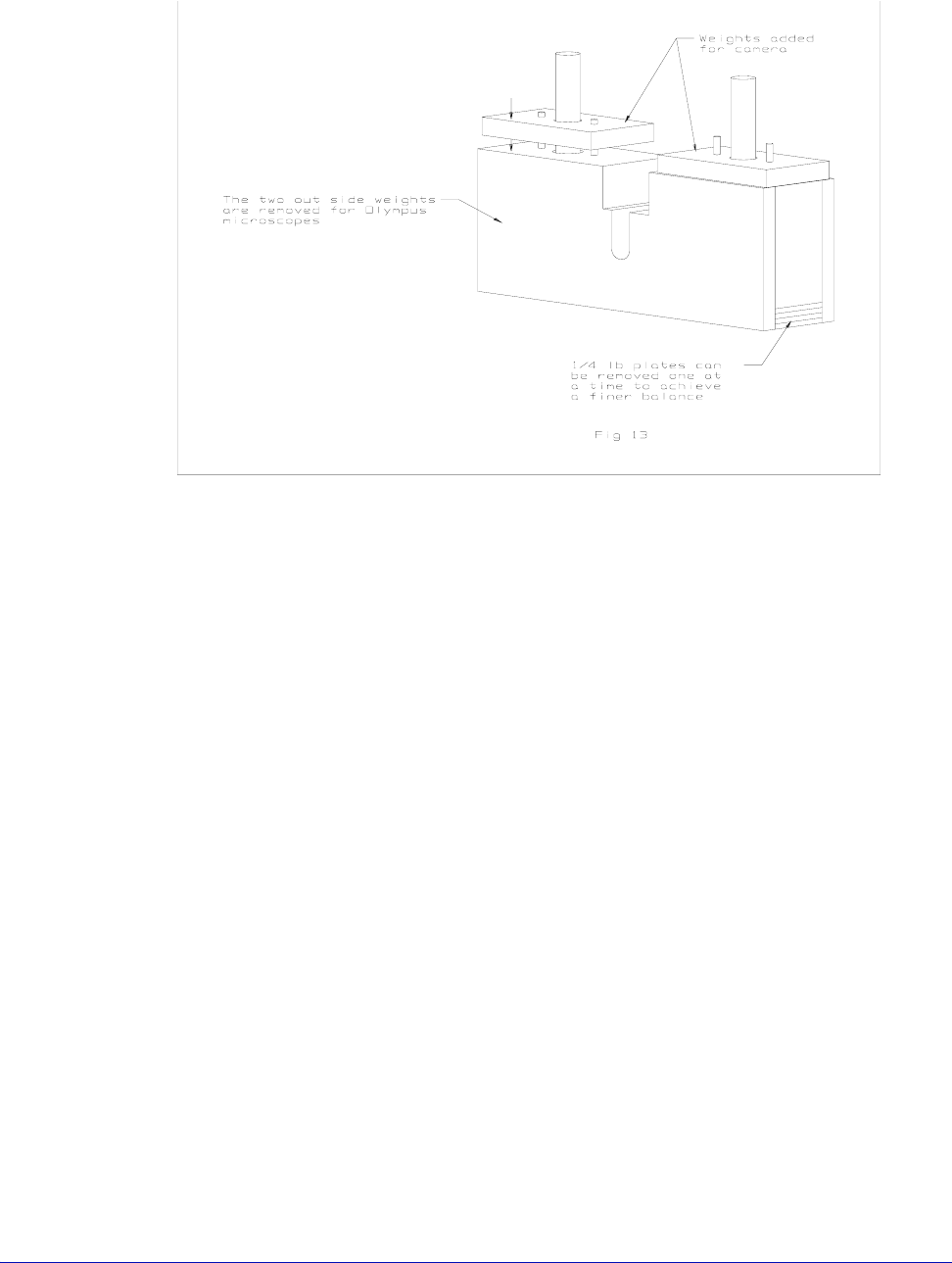
For information
about ordering
counterweights in
addition to the two
provided with the
optics bridge,
contact your
Cascade sales
representative.
To planarize the large-area optics bridge
The optics bridge is factory-planarized to the top chuck of your station and
should not need to be replanarized. However, the procedure is presented here
should you ever need to replanarize in the field.
Materials needed
To replanarize the optics bridge, you need a dial indicator, 0-0.010 inch, with a
magnetic base, or a special fixture that attaches to the dovetail mount on the
bridge.
Procedure
1. Place a sheet of Mylar on the chuck for protection.
2. Attach the dial indicator to the dovetail assembly.
3. Ensure that the eight 10-32 setscrews are loose and that the eight 8-32
capscrews are tightened.
4. Move the bridge to the back of the station (-Y) so that the dial indicator
needle rests near the edge of the chuck.
5. Zero the indicator.
6. Move the bridge to the front of the station (+Y). If there is a change in the
indicator’s reading, you must replanarize.
7. Release the tension on the four 8-32 capscrews in front or back as applicable.
8. Adjust the front or back setscrews to bring the bridge into planarization.
Fig. 30. Adding weight to the counterbalance.
Chapter 3: Installing •
43
• If the indicator’s reading was positive, adjust the front setscrews on both sides
a thousandth of an inch past zero.
• If the indicator’s reading was negative, adjust the back setscrews on both sides
a thousandth of an inch past zero.
Note that tightening the 8-32 screws will bring the indicator reading back to
zero.
Recheck and repeat the steps if necessary.
If you have questions about replanarizing the optics bridge, contact your Cascade
Customer Service.
INSTALLING POSITIONERS AND PROBES
You can mount these positioner types on this probe station: magnetic or vacuum-
based DCM positioners and fixed-mount RF style positioners.
To mount positioners and adjust probes, see the following documents:
• Microwave Probe Positioner User Guide (P/N 101-179)
• RF Positioner Installation Instructions (P/N 106-338)
To mount DCM positioners
Except for the rear port that interferes with the microscope, you can mount the
DCM positioner at any seal in the TopHat, if you have a MicroChamber. See
figure 36.
Procedure
1. Lower the Z-lever to lower the platen. This position keeps the probe head
from crashing into the chuck after installation.
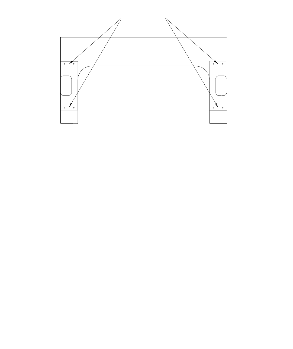
Holes for Adjustment
Screws (8)
Fig. 31. Screw location for planarization.
44
• Summit 11K/12K Probe Station User’s Guide
C
AUTION
Positioners are precision instruments, so handle them carefully. Avoid bumping or
dropping the positioners. Avoid handling that scratches or causes burrs on mating
surfaces.
2. Inspect the surface of the positioner, the positioner mounting plate, and the
platen. They should be free of contaminants.
3. Adjust the Z-axis knob counterclockwise to raise the positioner all the way
up. This ensures clearance between the chuck top and the probe you install.
4. Set the X-axis and Y-axis knobs in the center of their range.
5. Place the positioner close to where you want it once you mount the probe.
6. If this is a vacuum positioner, connect vacuum to one of the vacuum barbs on
the connection panel and flip the switch on (up position).
7. Mount probes and probe cables.
To connect positioner vacuum
The optional vacuum manifold provides six to ten vacuum connectors for
Cascade's vacuum-mounted DC positioners. On the large-area optics bridge,
these vacuum connectors are in the center of the connection panel, on the rear of
the platen. On the high-stability optics bridge, the vacuum connectors are located
on the left and right sides, under the bridge.
1. Attach 1/16-inch (inside diameter) hoses to each DCM positioner vacuum
base.
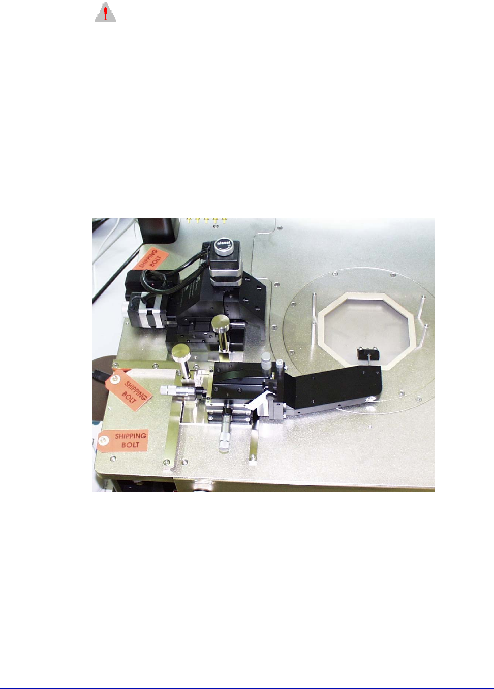
Fig. 32. MS1 positioner (without arm) and a south-positioned mount on platen.