晶圆测试说明书Cascade-11861-6-Manual.pdf - 第70页
46 • Summit 11K/12K Probe Station User’ s Guide T o install the positioners one at a time 1. Lower the Z-lever. C AUTION P ositioners are prec ision instr uments, so handle them car efully . A void bumping or dropping th…
Chapter 3: Installing •
45
2. Attach the other end of each hose to a connector on the connection panel.
3. Attach an 1/8-inch (inside diameter) hose from the connector on the back of
the vacuum manifold to your vacuum pump.
NOTE
With enough capacity, you can use the same vacuum pump for both the chuck
vacuum and the vacuum manifold. Otherwise, use separate vacuum pumps.
To use the same vacuum pump for the chuck vacuum and the vacuum manifold,
use a tee fitting to connect into the vacuum hose attached to the rear of the probe
station.
4. Flip on (“up” position with switch configuration or push-in with valve
configuration) all the vacuum connectors that you are using. Turn off all
unused connectors.
CAUTION
Loss of vacuum can cause probe tips to crash. Be careful not to accidentally turn
off any vacuum connectors or the vacuum pump.
If you are using the same vacuum pump for both the chuck vacuum and the
positioner vacuum, loss of vacuum can cause loss of hold down for your wafer and
positioners.
5. Turn on the vacuum pump.
6. While holding down the vacuum release valve on the positioner base,
position the DCM positioner.
7. Release the vacuum release valve to clamp the DCM positioner in place.
MOUNTING RF POSITIONERS
East-west
positioners are 0°
positioners; north-
south positioners
are 90° positioners.
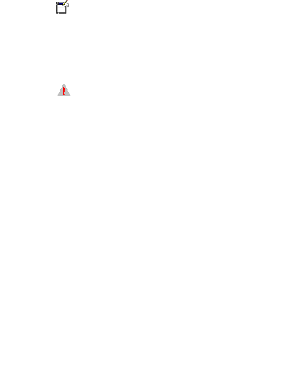
You can mount up to four RF positioners in the fixed positions on the platen. See
figure 33 on p. 46.
To use four RF probes on the probe station, you need two 0° positioners and two
90° positioners. You mount the 0° positioners on the platen's right and left sides
and the 90° positioners on the platen's front and rear sides.
46
• Summit 11K/12K Probe Station User’s Guide
To install the positioners one at a time
1. Lower the Z-lever.
CAUTION
Positioners are precision instruments, so handle them carefully. Avoid bumping or
dropping the positioners. Avoid handling that may cause scratches or burrs on
mating surfaces.
2. Inspect the surface of the positioner, the positioner mounting plate, and the
platen. They should be free of contaminants.
3. Adjust the Z-axis micrometer counterclockwise to raise the positioner all the
way up. This ensures clearance between the chuck top and the probe you
install.
4. Set the X-axis and Y-axis micrometers to half (between index mark 2 and 3) of
their range.
5. Mount the two rails to the platen, using the four mounting screws.
6. Slide the positioner between the rails.
CAUTION
The positioner can scratch the chuck top if it tilts forward and falls.
7. Mount the positioner close to where you want the probe mounted. The
standard position is to mount the positioner's front flush with the end of the
rails. For wider probe separation, mount the positioner farther away from the
wafer chuck.
8. Secure each positioner to the platen by tightening the clamping knob.
Fig. 33. Positioner configuration for four probes.
Chapter 3: Installing •
47
9. Check the positioner for clearance. The probe mount rests approximately 8
mm to 13 mm (0.3 inch to 0.5 in.) above the chuck top.
10.Mount the probes and probe cables.
11.Planarize the probe head. See ACP probe documentation.
INSTALLING THE PROBE CARD HOLDER
See the instructions that are included with the probe card holder.
INSTALLING THE TOPHAT
(MicroChambered Stations Only)
To install the MicroChamber TopHat
1. Remove the blank seals from the positioner entry areas.
2. Screw in the four standoffs on the platen. See figure 36 on p. 48.
3. Insert the TopHat ring on top of the platen.
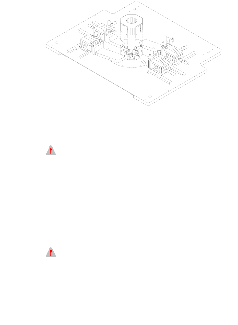
Fig. 34. Exit box (rear view).
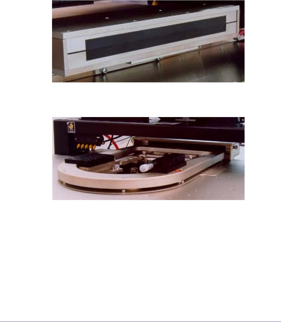
Fig. 35. Probe card holder.