晶圆测试说明书Cascade-11861-6-Manual.pdf - 第80页
56 • Summit 11K/12K Probe Station User’ s Guide V ERIFYING THE R OLL -O UT S TAGE The roll-out stage prov ides safe access to th e chuck. The roll-ou t handle is on the center front of the stage. Follow these steps to ve…
Chapter 4: Verifying and Operating •
55
VERIFYING X- AND Y-AXIS STAGE MOVEMENTS
See a prober control
software User’s
Guide (PCS or
Nucleus) and online
Help for more
details on
semiautomatic X-Y
stage movement.
You can control the X-Y stage with a mouse, a joystick, manually, or semi-
automatically. You find the X-and Y- and theta controls at the front of the probe
station near the base of the stage (fig. 43).
1. Turn the Y-axis control clockwise to move the stage forward. Reverse
rotation to move the stage backward.
2. Turn the X-axis control clockwise to move the stage to the right. Reverse
rotation to move the stage to the left.
For 11000-series
only: Repeat steps 3
and 4 for the other
X-axis control.
Turn the theta control clockwise to rotate the chuck top counterclockwise.
Reverse rotation to rotate the chuck top clockwise.
If the stage does not move as expected, check the following:
• That you removed the X-Y and roll-out stage shipping restraints.
• That the stage is not jammed by a stray piece of shipping material.
• If the stage still does not move, contact your Cascade representative
VERIFYING THETA ADJUSTMENTS
The theta control is on the right front of the stage. Follow these steps to verify the
theta control:
1. 1. Turn the theta control clockwise. The chuck top rotates counter-clockwise.
2. 2. Turn the theta control counterclockwise. The chuck top rotates clockwise.
If the chuck does not rotate as expected, make sure that it is not jammed by a stray
piece of shipping material.
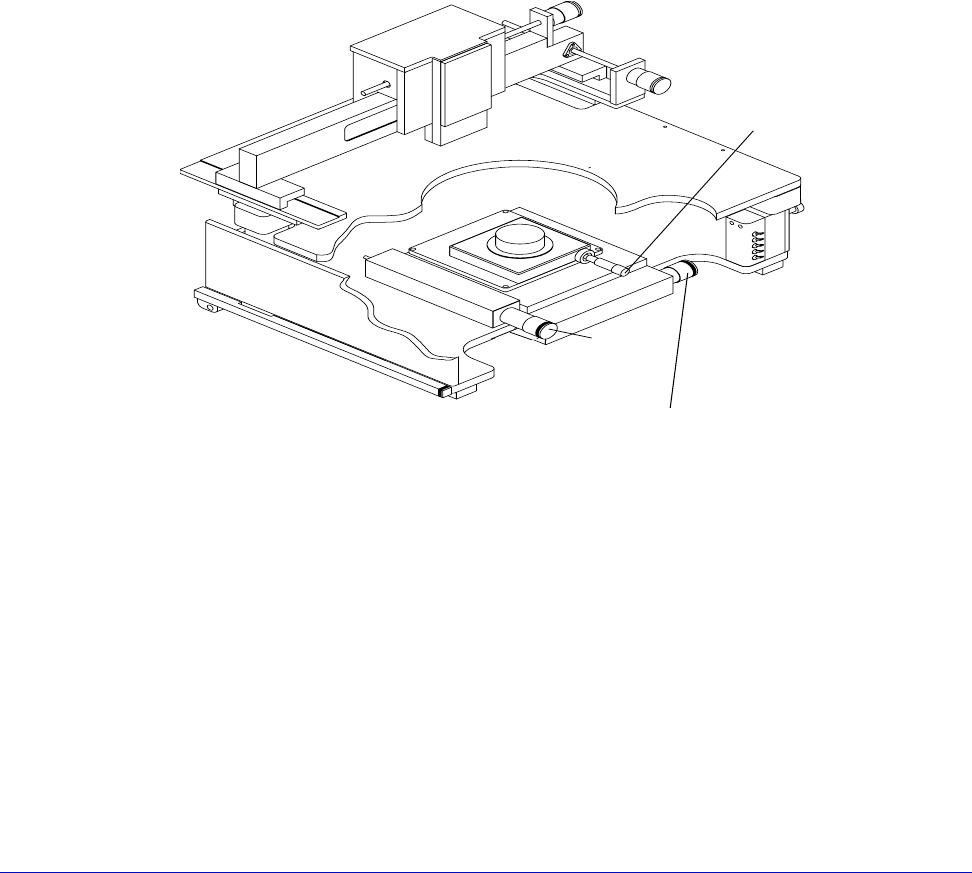
Fig. 43. Summit 12000-series station controls.
y-axis
control
Theta
control
x-axis control
56
• Summit 11K/12K Probe Station User’s Guide
VERIFYING THE ROLL-OUT STAGE
The roll-out stage provides safe access to the chuck. The roll-out handle is on the
center front of the stage. Follow these steps to verify the roll-out stage handle:
1. Raise the Z-lever.
WARNING
If the Z-lever is down when you pull the roll-out stage handle, you may scrape the
probes across the chuck and substrate, damaging the probes or wafer.
2. Open the MicroChamber access door.
3. Turn the roll-out stage handle counterclockwise to unlock the roll-out stage.
4. Pull the roll-out stage handle toward you. The stage slides smoothly to the
front of the probe station. With the stage in this forward position, you can
safely load and unload wafers to and from the chuck.
5. Push the roll-out stage handle back toward the stage. The stage slides
smoothly back and clicks gently into its lock.
6. Turn the roll-out stage handle clockwise to lock the roll-out stage in place.
If the stage does not roll out as expected, check that you removed the roll-out
stage shipping restraints
.
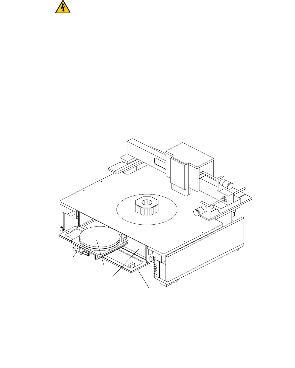
Fig. 44. Roll-out stage.
Roll-out
stage
handle
Chuck
MicroChamber
MicroChamber
access door
Chapter 4: Verifying and Operating •
57
VERIFYING CHUCK VACUUM CONTROLS
A bank of toggle switches lets you turn vacuum on and off at 13 mm
(0.5 in.), 75 mm (3 in.), and 150 mm (6 in.) diameters. See table 3.
NOTE
On a 12000-series station, the 13 mm (0.5 in.) toggle switch is replaced by prober
control software.
Table 3. Vacuum switch settings
The auxiliary stage
vacuum is
independent from
the main wafer
stage vacuum.
The vacuum control switches are under the platen on the probe station’s right-
front corner. See figure 41 on p. 53. The top two toggle switches control the
vacuum to the front and back auxiliary stages. The bottom three switches control
the vacuum to the holes in the chuck
.
Follow this procedure to verify the chuck vacuum:
1. Turn on your vacuum source.
2. Place a small piece of paper in the chuck’s center.
3. On an 11000-series station, turn on the switch labeled 13 mm to turn on
vacuum to the smallest vacuum area, 13 mm (0.5 in.).
On a 12000-series station, turn on the vacuum using PCS software.
4. Verify that the vacuum’s force holds the paper to the chuck top.
5. Repeat steps one through four to verify each vacuum area.
Chuck Diameter 13 mm switch 75 mm switch 150 mm switch
3 in.ONONOFF
0.5 in. ON OFF OFF
6 in.ONONON
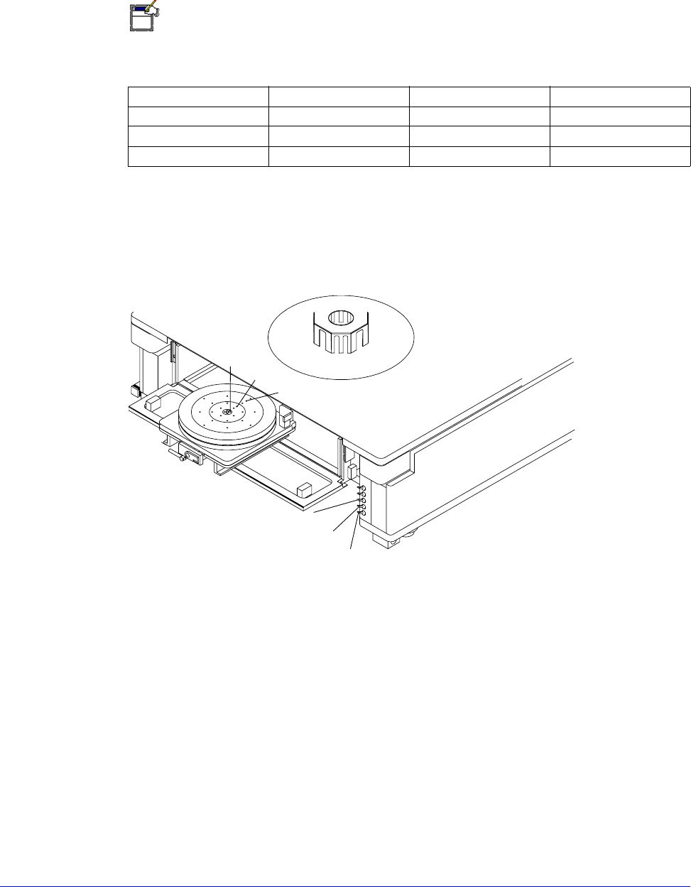
Fig. 45. Chuck vacuum zones.
Zone 1
Zone 2
Zone 3
Zone 1
Zone 2
Zone 3