晶圆测试说明书Cascade-11861-6-Manual.pdf - 第81页
Chapter 4: Verifying and Operating • 57 V ERIFY ING C HUCK V ACUUM C ONTROLS A bank of toggle switches lets you turn vacuum on and off at 13 mm (0.5 in.), 75 mm (3 in.), an d 150 mm (6 in.) diameters. See table 3. N OTE …
56
• Summit 11K/12K Probe Station User’s Guide
VERIFYING THE ROLL-OUT STAGE
The roll-out stage provides safe access to the chuck. The roll-out handle is on the
center front of the stage. Follow these steps to verify the roll-out stage handle:
1. Raise the Z-lever.
WARNING
If the Z-lever is down when you pull the roll-out stage handle, you may scrape the
probes across the chuck and substrate, damaging the probes or wafer.
2. Open the MicroChamber access door.
3. Turn the roll-out stage handle counterclockwise to unlock the roll-out stage.
4. Pull the roll-out stage handle toward you. The stage slides smoothly to the
front of the probe station. With the stage in this forward position, you can
safely load and unload wafers to and from the chuck.
5. Push the roll-out stage handle back toward the stage. The stage slides
smoothly back and clicks gently into its lock.
6. Turn the roll-out stage handle clockwise to lock the roll-out stage in place.
If the stage does not roll out as expected, check that you removed the roll-out
stage shipping restraints
.
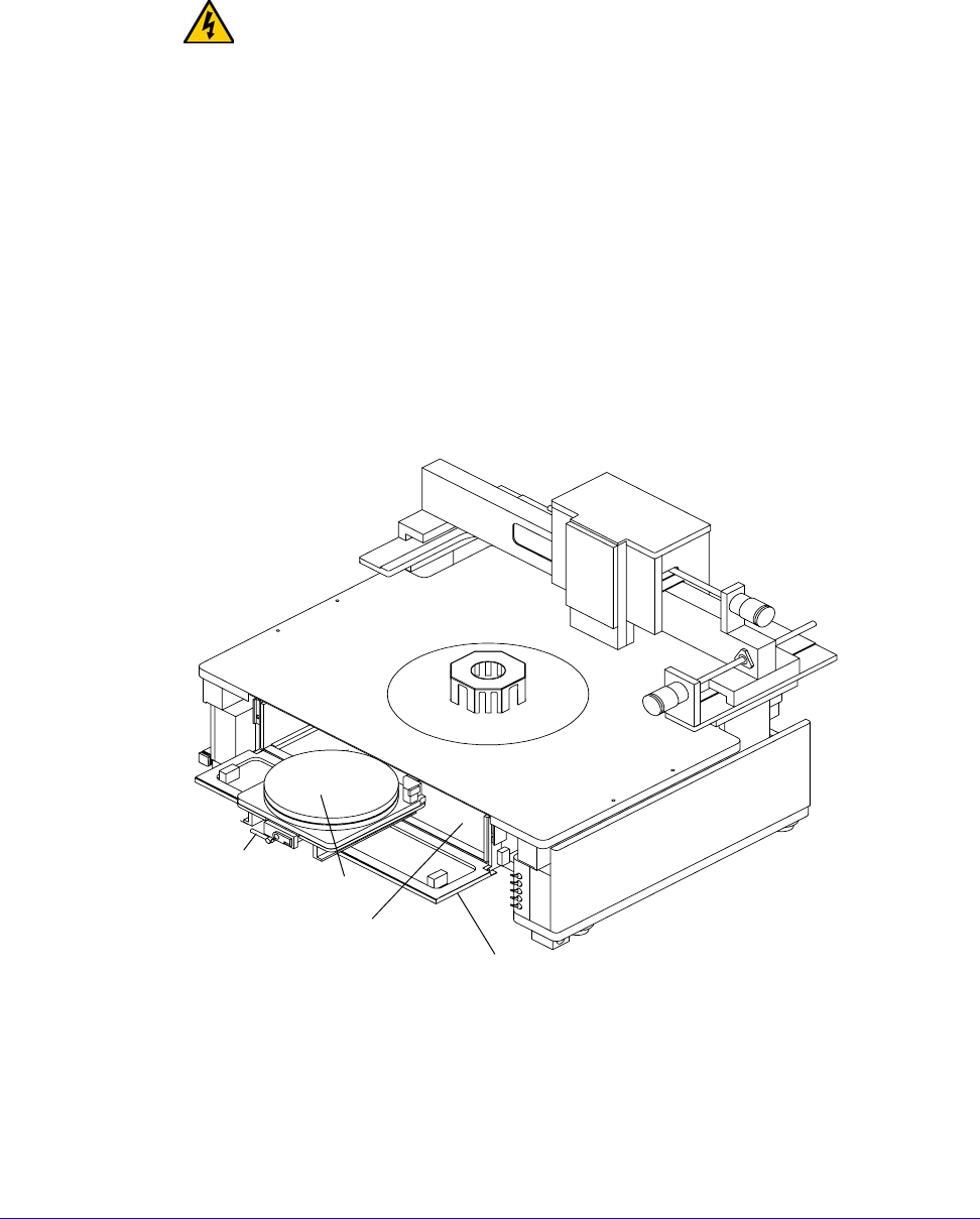
Fig. 44. Roll-out stage.
Roll-out
stage
handle
Chuck
MicroChamber
MicroChamber
access door
Chapter 4: Verifying and Operating •
57
VERIFYING CHUCK VACUUM CONTROLS
A bank of toggle switches lets you turn vacuum on and off at 13 mm
(0.5 in.), 75 mm (3 in.), and 150 mm (6 in.) diameters. See table 3.
NOTE
On a 12000-series station, the 13 mm (0.5 in.) toggle switch is replaced by prober
control software.
Table 3. Vacuum switch settings
The auxiliary stage
vacuum is
independent from
the main wafer
stage vacuum.
The vacuum control switches are under the platen on the probe station’s right-
front corner. See figure 41 on p. 53. The top two toggle switches control the
vacuum to the front and back auxiliary stages. The bottom three switches control
the vacuum to the holes in the chuck
.
Follow this procedure to verify the chuck vacuum:
1. Turn on your vacuum source.
2. Place a small piece of paper in the chuck’s center.
3. On an 11000-series station, turn on the switch labeled 13 mm to turn on
vacuum to the smallest vacuum area, 13 mm (0.5 in.).
On a 12000-series station, turn on the vacuum using PCS software.
4. Verify that the vacuum’s force holds the paper to the chuck top.
5. Repeat steps one through four to verify each vacuum area.
Chuck Diameter 13 mm switch 75 mm switch 150 mm switch
3 in.ONONOFF
0.5 in. ON OFF OFF
6 in.ONONON
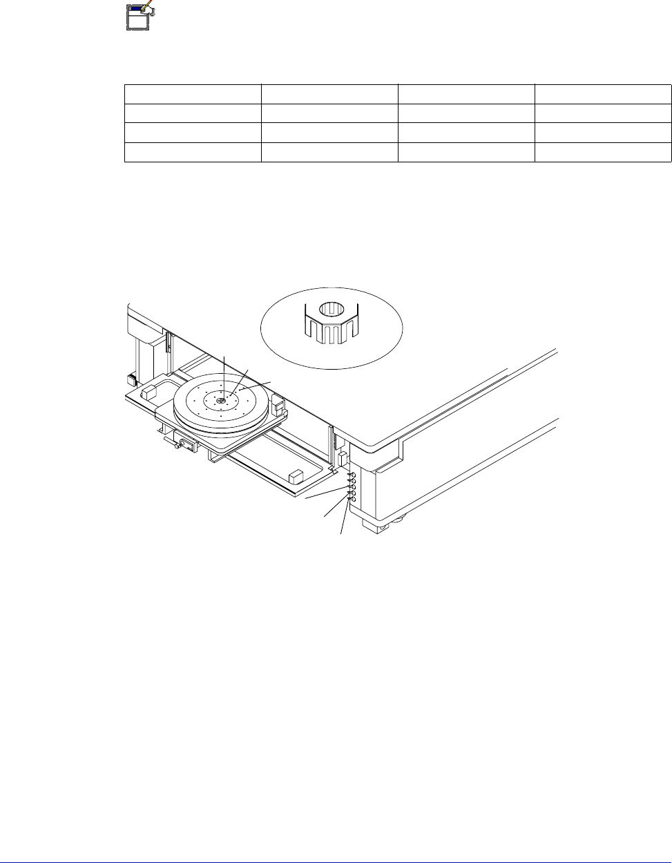
Fig. 45. Chuck vacuum zones.
Zone 1
Zone 2
Zone 3
Zone 1
Zone 2
Zone 3
58
• Summit 11K/12K Probe Station User’s Guide
For example, for a small device or 2-inch wafer, turn on the switch labeled 13 mm.
For a 3-, 4-, or 5-inch wafer, turn on both the 13 mm and 75 mm switches. For a 6-
or 8-inch wafer, turn on all three switches
(13 mm, 75 mm, and 150 mm).
To turn off vacuum, flip all three switches to the off (down) position. If the paper
does not hold down as expected, make sure that:
• Your vacuum source works properly;
• The hose connects properly to both the vacuum source and to the probe
station.
VERIFYING THE MICROSCOPE AND VIDEO ADJUSTMENTS
CAUTION
TILT-BACK BRIDGE
Center the programmable scope transport before raising or lowering the tilt-back
bridge or damage can occur to the probe station and/or accessories. Scope travel
is limited to 1-inch in the x-, y-axes when using the TopHat.
Nucleus software supports the programmable scope transport if the optional
autoprobe module (PN 123-567) is purchased. This module controls the ECX-56
Box accessories.
1. Move the stage to its approximate center of X-Y travel.
2. Focus the microscope on the chuck top.
3. Move the stage in the X- and Y-axes, and check that the video on the monitor
moves in the same direction. If it travels in the opposite direction, the camera
is not properly placed on the adapter. Loosen the thumbscrews on the camera
and rotate it 180 degrees; then re-tighten.
4. Move the optics bridge in the X- and Y-axis and make sure that it travels
smoothly.
5. Place the microscope in the center of travel and focus on the chuck top.
6. Move the optics bridge in the X- and Y-axes and make sure that the
microscope stays in focus throughout its travel.
Verifying the 12000-Series Station with Software
NOTE
Two different software applications, PCS and Nucleus, are available for controlling
the Summit 12000-series semiautomatic probe stations. The following section
deals with PCS, which contains the “verify” program. If you are using Nucleus, see
the Nucleus User’s Guide.
The Verify software checks the probe station hardware except for the joystick,
which has its own test. Click the “Verify” icon to run the tests:
• During installation
• During preventive maintenance