00195374-0202_AI_LBO-D1D2_DE+EN.pdf - 第42页
2 Assembly instructions Long board op tion SIPLACE D1 / D2 Long board option 06/2007 Edition 42 : Unscrew the sonar sensor until th e distance fr om the fixing bracket to the end of the sonar sen - sor is 38 mm. : Fix th…
Long board option 2 Assembly instructions Long board option SIPLACE D1 / D2
06/2007 Edition
41
2.6 Assembling the Long board stopper
: Shut down the operating system and switch off the placement machine at the main switch.
2
The unit must be attached to the stationary conveyor side wall and the switch actuator to the mov-
ing side wall. 2
: Connect the connector on the unit to the connecting cable.
: Connect the hose to the quick-release coupling on the unit.
2
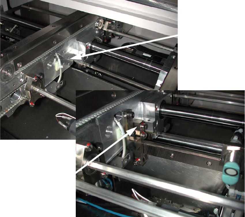
: Take the stopper and fix it using two screws (2x M6 x 30 screws) on the stationary conveyor
side wall (1 or 3), as shown in the picture. If the stationary conveyor side wall is on the left, the
stopper must be converted as described in the assembly instructions Chapter 2.11 and fitted
to the conveyor side wall (2 or 4).
: Set th
e stopper position using the
LBO D1/D2 assembly gauge.
The adjustments are carried out using the adjusting gauge (for the settings, see Section Chap-
ter 2.6.1).
Stationary conveyor side on the right
without stopper
Long PCB stopper, stationary conveyor side
on the right
2
2 Assembly instructions Long board option SIPLACE D1 / D2 Long board option
06/2007 Edition
42
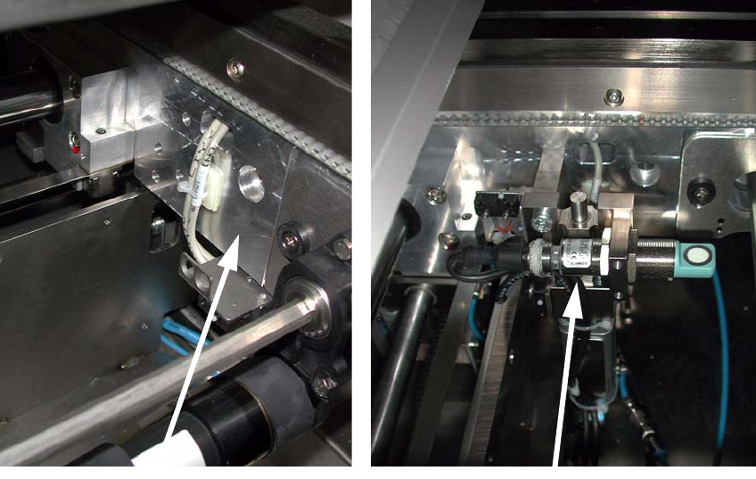
: Unscrew the sonar sensor until the distance from the fixing bracket to the end of the sonar sen-
sor is 38 mm.
: Fix the limit switch actuator to the moving conveyo
r side wall using two screws (2x M6 x 25
screws) as shown in the picture.
Moving conveyor side
wall on the left without
limit switch actuator
Limit switch actuator,
moving conveyor side
wall on the left
2
2
2
2
2
2
2
2
2
Long board option 2 Assembly instructions Long board option SIPLACE D1 / D2
06/2007 Edition
43
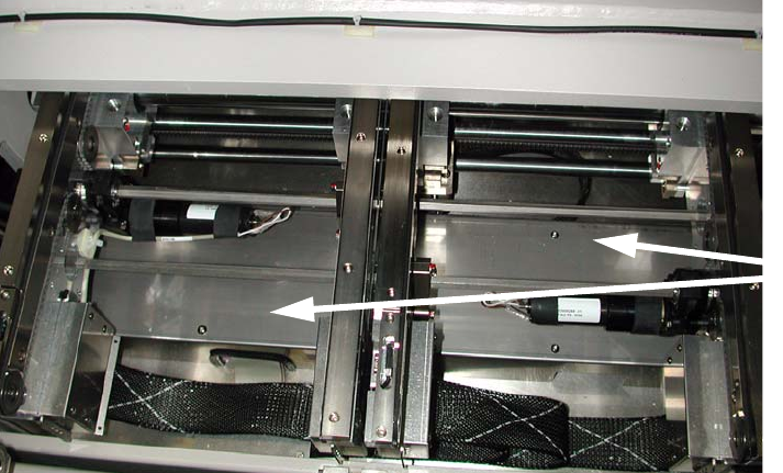
: Remove the cover over the conversion board (6 screws) beneath the output conveyor belt.
Cover
2
2
2
2
2
2
2
2
2
2
2
2
2
2
2
2
2
2
2