00195374-0202_AI_LBO-D1D2_DE+EN.pdf - 第46页
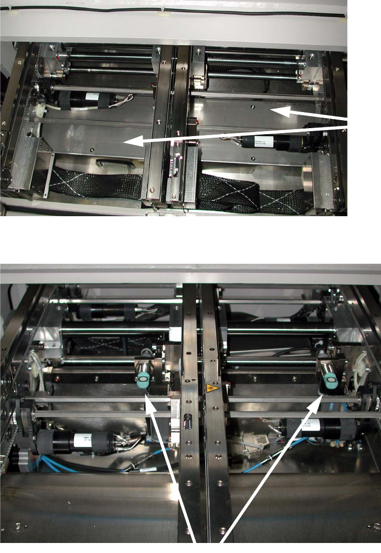
2 Assembly instructions Long board op tion SIPLACE D1 / D2 Long board option 06/2007 Edition 46 : Fit the cover over the conversion boa rd (6 screws) beneath th e output conveyor belt. Cover 2 The stoppers should now loo…
Long board option 2 Assembly instructions Long board option SIPLACE D1 / D2
06/2007 Edition
45
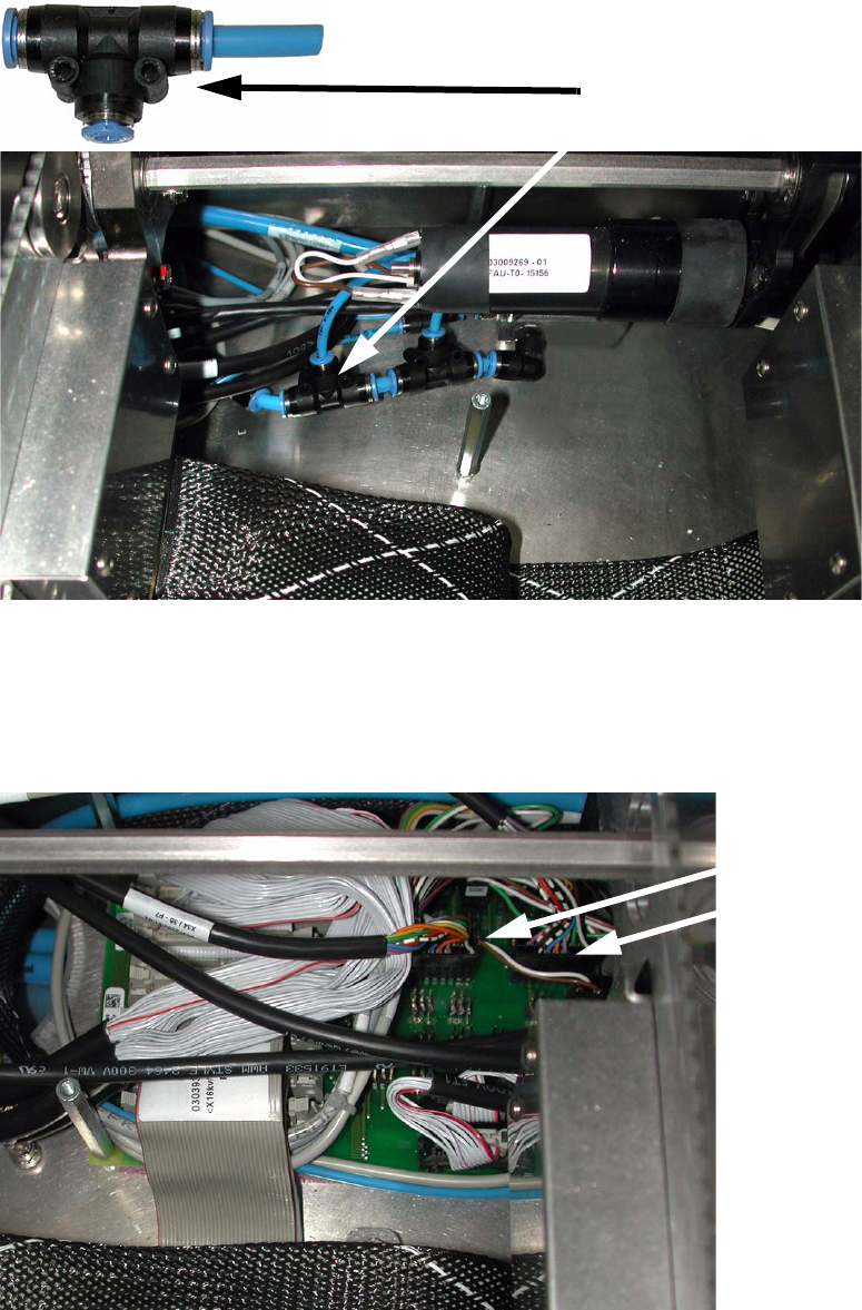
: Connect the air hose to the conveyor's pneumatic distributor using the T-piece.
T-piece
2
: Run the connecting cable to the conveyor conversion board, and plug the cable into the rele-
vant slots on the conversion board (00372253-01):
X34 for conveyor track 1,
X35 for conveyor track 2.
X34
X35
2
2 Assembly instructions Long board option SIPLACE D1 / D2 Long board option
06/2007 Edition
46
: Fit the cover over the conversion board (6 screws) beneath the output conveyor belt.
Cover
2
The stoppers should now look as follows (example of the dual conveyor): 2
Stopper
2
: Switch the placement machine on at the main switch and start the SITEST program.
Long board option 2 Assembly instructions Long board option SIPLACE D1 / D2
06/2007 Edition
47
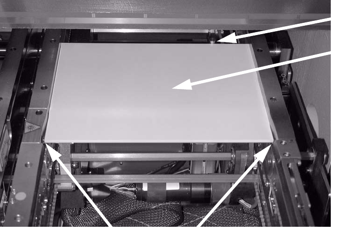
2.6.1 Adjusting the stopper units
: Set the conveyor width to 200 mm.
: Switch on the laser
light barrier via the I/O functions in SITEST (see section 1.7).
: Use the I/O functions to extend the stopper.
: Check that the distance between the laser light barrier and the stopper is 150 mm
using
th
e "LBO D1/D2 assembly gauge" (03049211-xx).
: Place the adjusting g
auge in the conveyor and push it against the stopper.
The gauge must lie against the stopper and the st
ationary conveyor side wall.
Adjusting
gauge
Stopper
Laser light barriers
2
2
: Place the adjusting gauge in the conveyor and push it against the stopper.
The gauge must lie against the stopper and the st
ationary conveyor side wall.
2
2
2
2
2
2