5OM-1343-008_w.pdf - 第211页
5-B AKFEPED-ID 0601-002

5-A
AKFEPED-ID
0601-002
Chapter 5
Cord Connection Diagrams
This chapter describes the cord connection diagrams.
As this contains highly sophisticated contents, it should
carefully be referred to.

5-B
AKFEPED-ID
0601-002
AKFEPED-ID
5-1
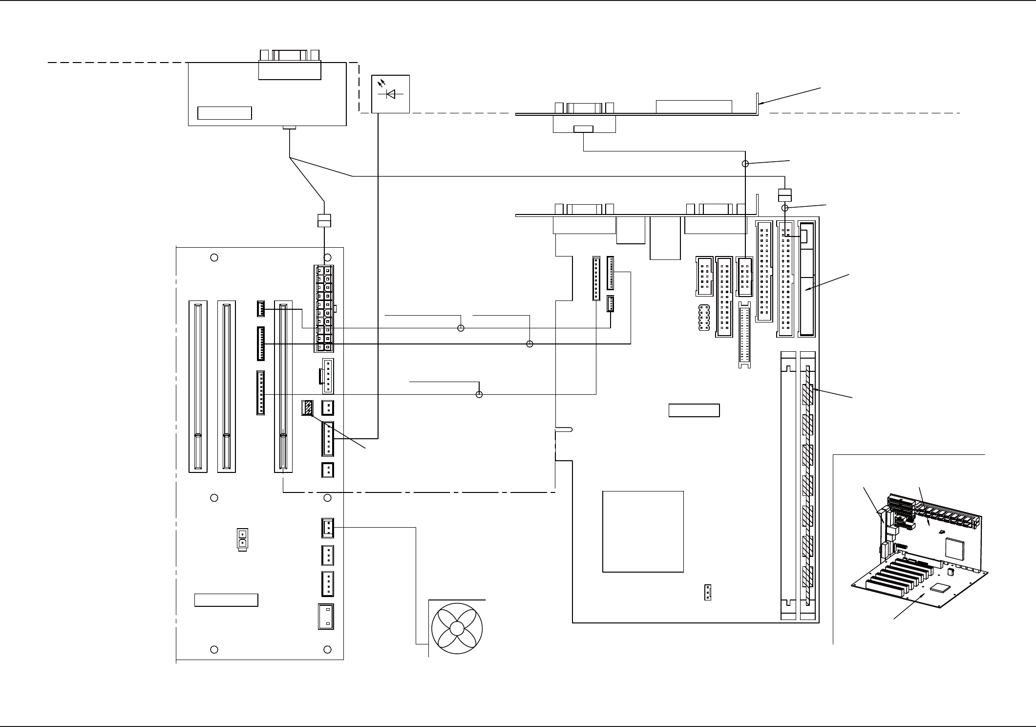
CPU2 Internal Connections
CPU2 Internal Connections
0909-005 F(M803JSB--2001)
FB)159 : 4W202793
(630 125 6498)
#KFT-049-01
BL/BR)352 : 4B111533
(630 141 4140)
HFPP-PIC8
DUX
CN1
CN1
CN2
CN3
CN4
CN9
CN13
CN10
CN8
CN6
CN7
CN19
CN18
CN14
CN16
CN15
CN17
CN1
CN2
CN3
CN4
CN5
CN6
CN7
CN8
CN9
CN10
CN11
CN12
CN13
CN14
CN15
CN16
CN17
COM2
RS232C
MASTER SLAVE
P2
P1
CN11
CN12
* Right CPU2
BR) S356 (DOM)
* Left CPU2
BL) S356 (DOM)
Case Fan
Power Unit
Case LED
Back Plane
The jumper (accessory part)
is connected to the back plane.
EXT Connector Cable
PAT-092
(provided together with
CPU board)
Provided together with FB)159
Provided together with FB)156
Memory (Provided)
CPU Board
CPU Board
COM2 Drawer Panel
Back Plane
RESET Port
Connector Cable PAT-311
(provided together with
CPU board)
COM2 Drawer Panel
RAS Port Connector Cable
PAT-309
(provided together with CPU board)