5OM-1343-008_w.pdf - 第57页
1-B AKFEPED-ID 0601-002

1-A
AKFEPED-ID
0601-002
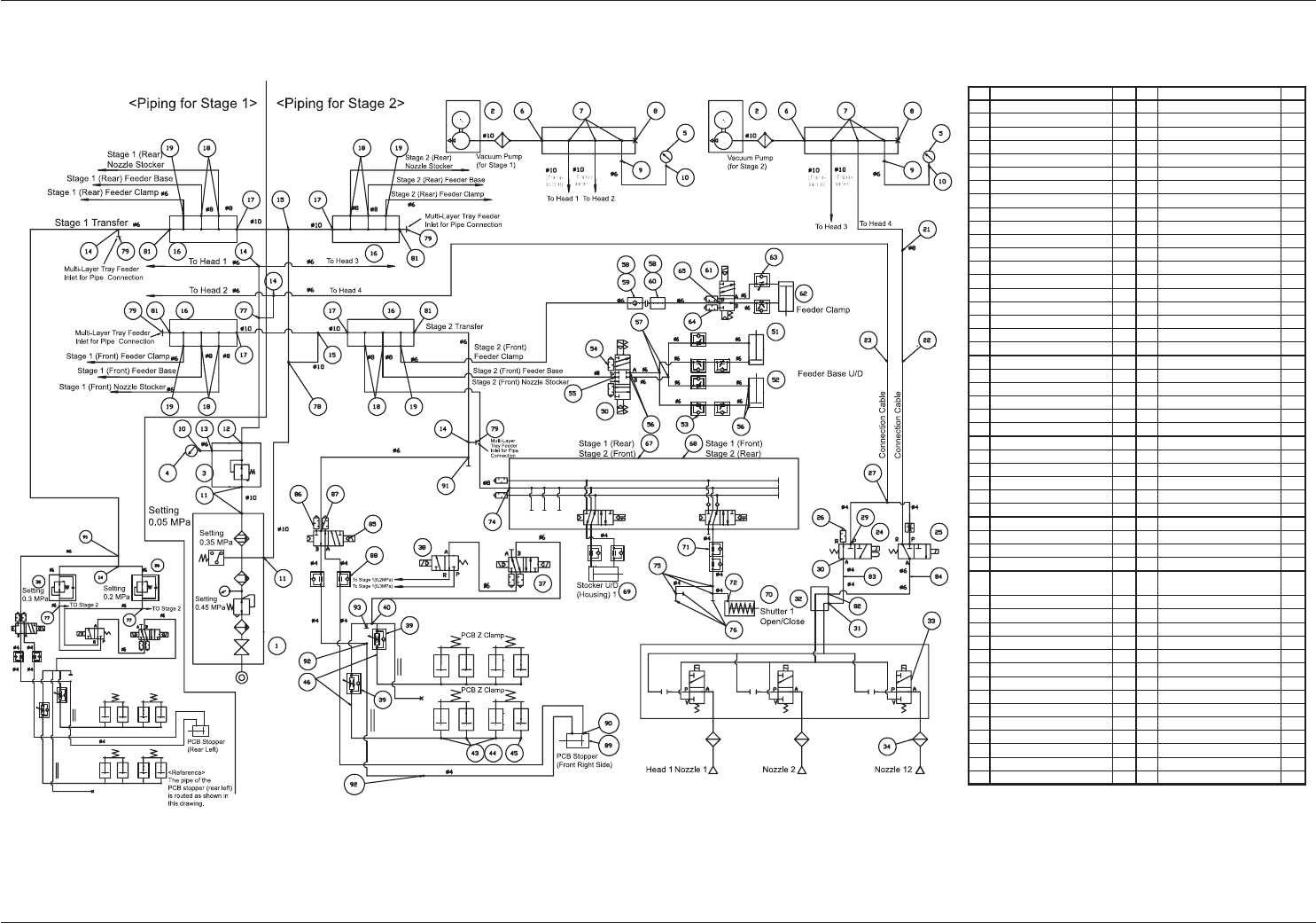
Chapter 1
Pneumatic Diagram
This chapter describes the pneumatic diagram.
As this contains highly sophisticated contents, it should
carefully be referred to.

1-B
AKFEPED-ID
0601-002
AKFEPED-ID
1-1
No. Name Q'ty No. Name Q'ty
1 Combination Unit 1 51 Cylinder 4
2 Vacuum Pump 2 52 Cylinder 4
3 Regulator 1 53 Speed Controller 24
4 Pressure Gauge 1 54 Silencer 8
5 Vacuum Gauge 2 55 Universal Elbow 4
6 Vacuum Gauge 2 56 Universal Elbow 24
7 Quick Universal Joint 6 57 Cheese 8
8 Plug 2 58 Modular Unit 8
9 Reducer 2 59 Air Contacting Pin 4
10 Half Union 3 60 Air Contacting Pin 4
11 Elbow Union 3 61 Solenoid Valve 4
12 Elbow Union 1 62 Cylinder 4
13 Half Union 1 63 Speed Controller 8
14 Union Y 5 64 Silencer 8
15 Union Y 2 65 Elbow Union 4
16 Manifold 4
17 Street Elbow 4 67 Solenoid Valve Unit 2
18 Street Elbow 8 68 Solenoid Valve Unit 2
19 Reducer Elbow 4 69 Cylinder Unit 4
70 Cylinder 4
21 Different Union 4 71 Speed Controller 8
22 Bulkhead Union 4 72 Barbed Elbow 4
23 Bulkhead Union 4
24 Solenoid Valve 4 74 Half Union 4
25 Solenoid Valve 4 75 Union Y 12
26 Silencer 4 76 Plug 12
27 Different Union Y 4 77 Cheese 3
78 Cheese 1
29 Elbow Union 4 79 Plug 4
30 Half Union 4
31 Half Union 4 81 Reducer Elbow 4
32 Rotary Joint 4 82 Half Union 4
33 Solenoid Valve 48 83 Elbow 2
34 Filter 96 84 Elbow 2
85 Solenoid Valve 2
36 Pressure Gauge Unit 2 86 Half Union with Hexagonal
Head
2
37 Solenoid Valve Unit 2 87 Silencer 4
38 Solenoid Valve Unit 2 88 Speed Controller 4
39 Speed Controller 4 89 Cylinder 2
40 Different Double Union Y 2 90 Barbed Elbow 4
91 Union Y 2
92 Half Union 4
43 Universal T 12 93 Plug 2
44 Barbed Fitting 24
45 Barbed Elbow 4
46 Flat Tube 4
50 Solenoid Valve 4
Pneumatic Diagram
0607-004 E(M803XA---0021)
Pneumatic Diagram