5OM-1343-008_w.pdf - 第61页
2-B AKFEPED-ID 0601-002

2-A
AKFEPED-ID
0601-002
Chapter 2
Layout of Sensors and Loads
This chapter indicates where the sensors and loads are
located in each section.
As this contains highly sophisticated contents, it should
carefully be referred to.

2-B
AKFEPED-ID
0601-002
2-1
AKFEPED-ID
0604-003
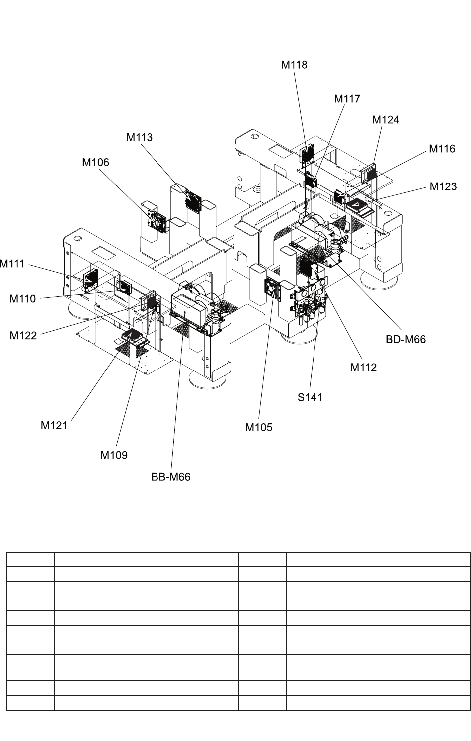
Layout of Sensors and Loads Underframe
Layout of Sensors and Loads Underframe
Symbol Name Symbol Name
BB-M66 Vacuum Pump 1 BD-M66 Vacuum Pump 2
M105 Underframe Cooling Fan (Front Left Side) M112 Underframe Cooling Fan (Front Right Side)
M106 Underframe Cooling Fan (Rear Left Side) M113 Underframe Cooling Fan (Rear Right Side)
M109
Underframe Left Side Cooling Fan (Front Side)
M116
Underframe Right Side Cooling Fan (Front Side)
M110
Underframe Left Side Cooling Fan (Rear Side
)M117
Underframe Right Side Cooling Fan (Rear Side)
M111 CPU2 (Left) Cooling Fan M118 CPU2 (Right) Cooling Fan
M121
CPU2 (located above the power unit)
Cooling Fan (Left)
M123
CPU2 (located above the power unit)
Cooling Fan (Right)
M122
Conveyer Multiaxis Amplifi er Cooling Fan (Left)
M124
Conveyer Multiaxis Amplifi er Cooling Fan (Right)
S141 Pressure Switch