PS288_OwnersMnl_PriorTo2009 - 第100页
Operation • Administrato r Functions 3—40 PS288 Owner’s Manual 3e) Click X,Y AutoFind . Figur e 3-56—Click X,Y AutoFind 3f) If the new values for X and Y are >±5, press Ye s and repeat Step 3e. If the new values for X…
Operation • Administrator Functions
PS288 Owner’s Manual 3—39
2f) If the new values for X and Y are >±5, press Yes and repeat Step 2e.
If the new values for X and Y are <±5, press No.
3. Teach lower right corner of Tray 1—
3a) Select the Trays tab.
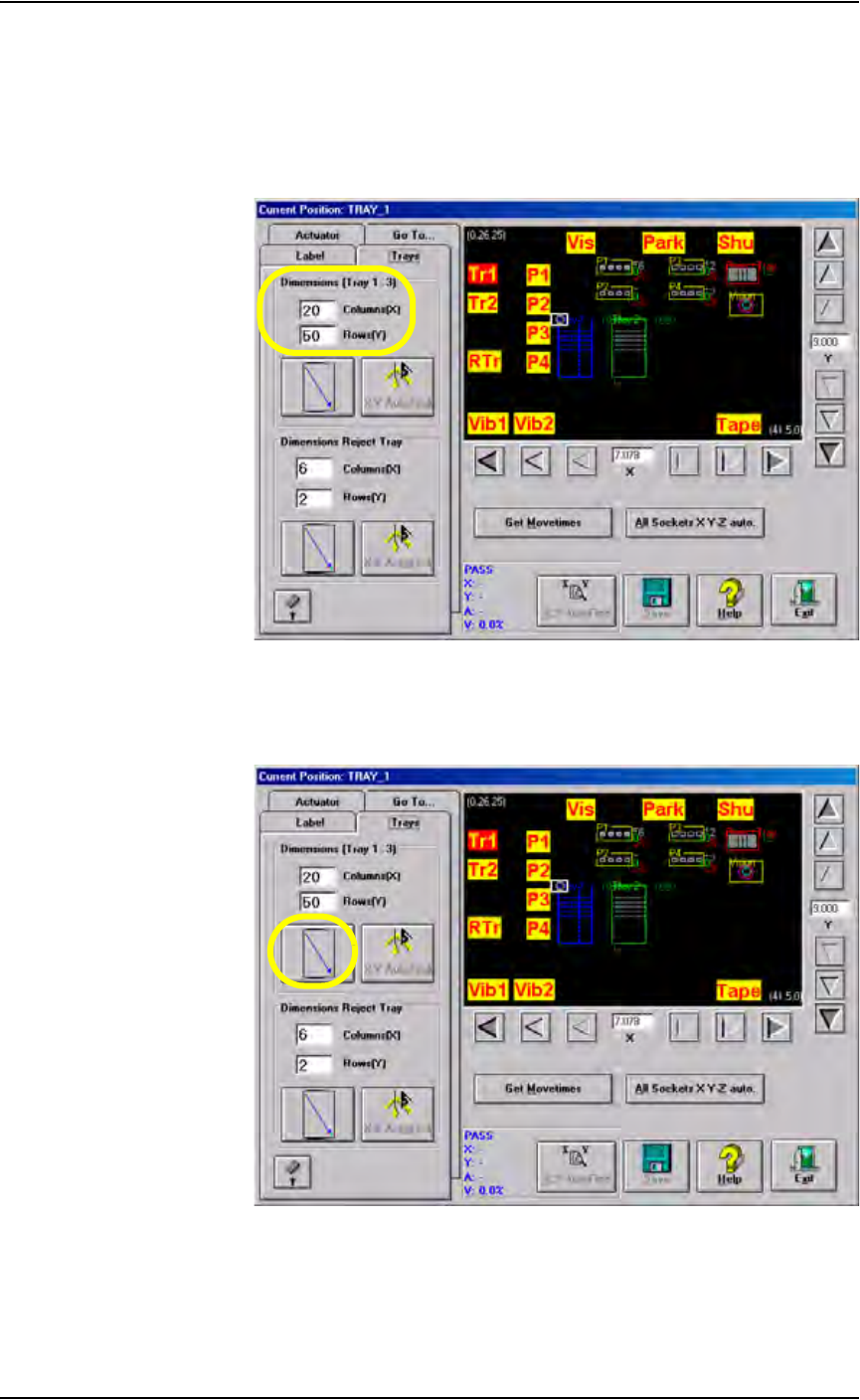
3b) Enter the number of columns and rows for this tray. See Figure 3-54.
Figure 3-54—Specify dimensions of Tray 1
3c) Click the diagonal arrow. See Figure 3-55. The PNP head moves to the
lower right corner of Tray 1.
Figure 3-55—Click diagonal arrow
3d) Adjust the location of the probe tip so that it is centered on the device
in the lower right corner of Tray 1. Use the up/down arrows for Y-axis
adjustments and the left/right arrows for X-axis adjustments.
Operation • Administrator Functions
3—40 PS288 Owner’s Manual
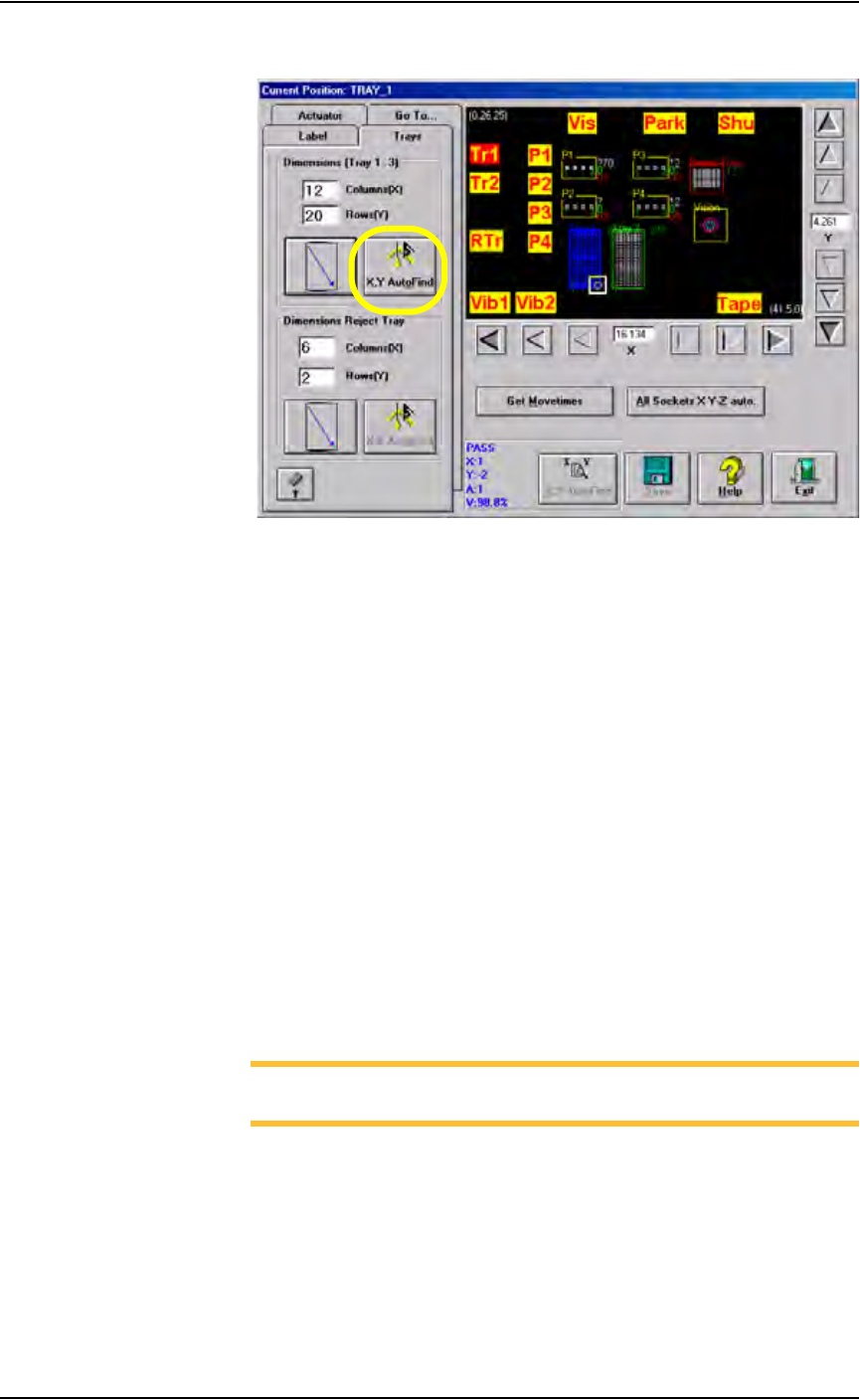
3e) Click X,Y AutoFind.
Figure 3-56—Click X,Y AutoFind
3f) If the new values for X and Y are >±5, press Yes and repeat Step 3e.
If the new values for X and Y are <±5, press No.
4. Teach Tray 2 location—
4a) Click Tr2.
4b) Adjust the location of the probe tip so that it is centered on the device
in the upper left corner of Tray 2. Use the up/down arrows for Y-axis
adjustments and the left/right arrows for X-axis adjustments.
4c) Click Save.
4d) Click Z AutoFind. The PNP head lowers and the probe tip touches the
device. Click Yes to save the new values. The Z-axis reference position
is now set.
4e) Click X,Y AutoFind. The PNP head picks the device, takes it to Vision
system and compares the orientation of the device to the orientation in
the reference vision file.
4f) If the new values for X and Y are >±5, press Yes and repeat Step 4e.
If the new values for X and Y are <±5, press No.
5. Teach Reject location—
NOTE: See Figure 2-6 for possible physical location of reject
box/bin.
5a) Click RTr.
5b) Adjust the location of the probe tip so that it is centered at the upper left
corner of the reject box/bin. Use the up/down arrows for Y-axis adjust-
ments and the left/right arrows for X-axis adjustments.
5c) Click Save.
5d) Select the Trays tab.
Operation • Administrator Functions
PS288 Owner’s Manual 3—41
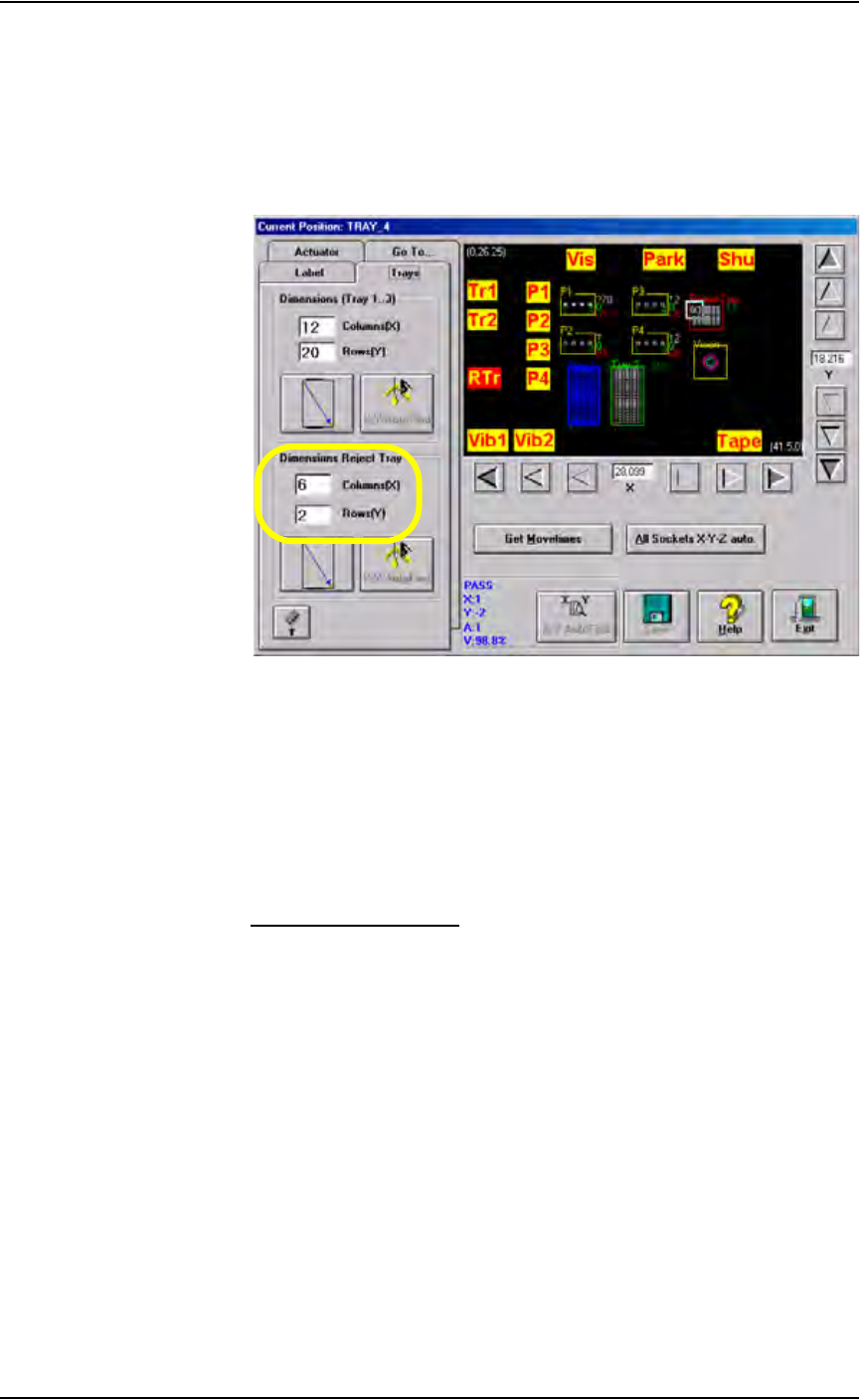
5e) In the Dimensions Reject Tray field, enter a value for Columns (X) and
Rows (Y) for the reject box/bin. These values set the number of reject
devices sent to the reject box/bin before the Reject is Full message is
displayed. In the example shown in Figure 3-57, the Reject is Full
message is displayed after 12 (6 x 2 = 12) devices are placed in the
reject tray.
Figure 3-57— Setting number of devices sent to reject tray
5f) Click the diagonal arrow. The PNP head moves to the lower right cor-
ner of the reject tray.
5g) Adjust the location of the probe tip so that it is centered at the lower
right corner of the reject tray. Use the up/down arrows for Y-axis
adjustments and the left/right arrows for X-axis adjustments.
5h) Click Save.
5i) When prompted, click Ye s to overwrite values.
Teach Tube Locations
1. Prepare the system—
1a) From the AH500 Setup window, select the Options tab.
1b) For main Input and Output media, select Tubes.
1c) For Reject 1, select Vibrator 2.
1d) In the Count of Fail Tubes field, enter the number of tubes in Vibrator
2 (output feeder) that will receive failed (reject) devices.
1e) Insert tubes in Vibrator 1 (input feeder) and Vibrator 2 (output feeder).
2. Teach Vibrator 1 locations—
2a) On the Gantry window, click Vib1.