PS288_OwnersMnl_PriorTo2009 - 第105页
Operation • Administrator Functi ons PS288 Owner’s Manual 3—45 1b) Click Ye s when prompted to save positions. Figur e 3-61—Save positions 1c) W ait for the calculation to finish. This completes the process of teaching t…
Operation • Administrator Functions
3—44 PS288 Owner’s Manual
Teach Tape-Input Location
1. Prepare the system—
On the feeder unit control panel, press and hold the center button.
While holding the center button, press the forward button. The carrier
tape advances one guide hole. Advance the carrier tape in this manner
until the pick point mark on the tape window aligns with the center of
the device. A device is now in the pick location.
2. Teach locations—
2a) On the Gantry window, click Tape. The PNP head moves to the tape
input pick location.
2b) Adjust the location of the probe tip so that it is centered on the device
in the pick location of the feeder unit. Use the up/down arrows for
Y-axis adjustments and the left/right arrows for X-axis adjustments.
2c) Click Save.
2d) Click Z AutoFind. The PNP head lowers and the probe tip touches the
device.
2e) Click Yes to save the new values. The Z-axis reference position is now
set.
2f) Click X,Y AutoFind. The PNP head picks the device, takes it to Vision
system and compares the orientation of the device to the orientation in
the reference vision file.
2g) If the new values for X and Y are >±5, press Ye s and repeat Step 2f.
If the new values for X and Y are <±5, press No.
Get Movetimes
When the package file is taught, you can optimize the movement of the PNP
head in the work envelope by getting movetimes.
To get movetimes:
1. Gantry—
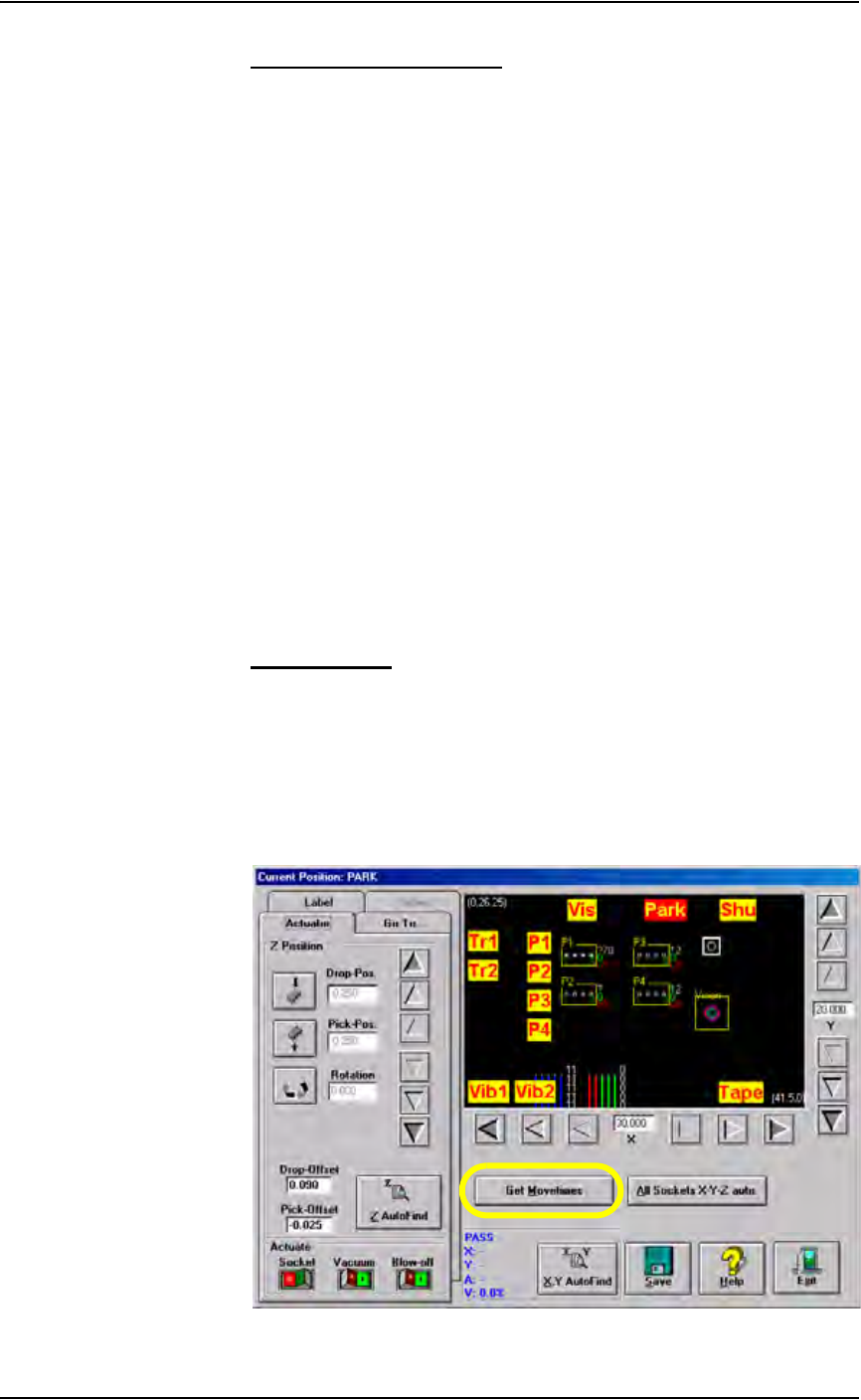
1a) On the Gantry window, click Get Movetimes.
Figure 3-60—Click Get Movetimes
Operation • Administrator Functions
PS288 Owner’s Manual 3—45
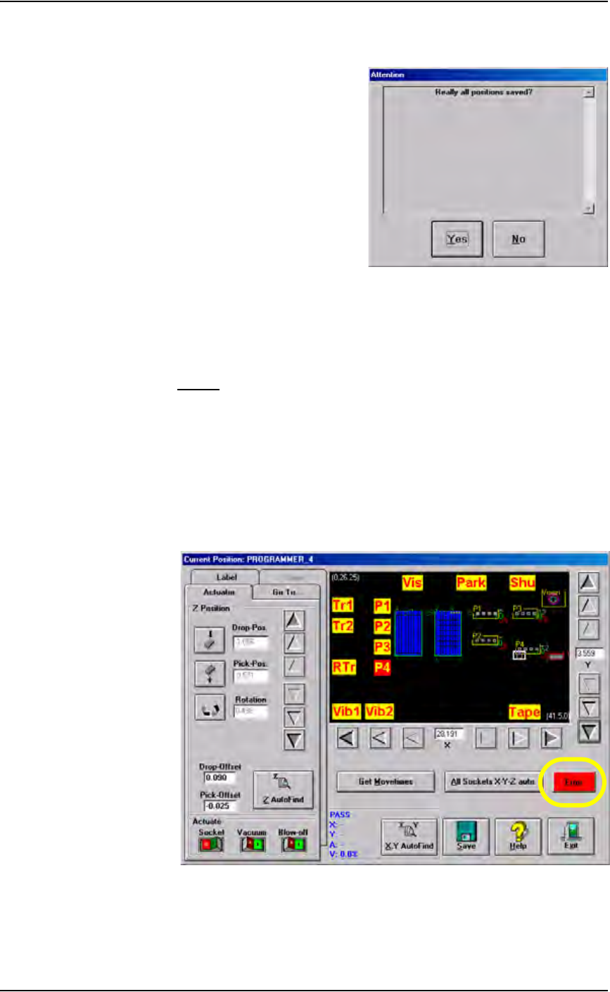
1b) Click Ye s when prompted to save positions.
Figure 3-61—Save positions
1c) Wait for the calculation to finish.
This completes the process of teaching the package file.
Errors
During the process of teaching the package file, you will be directing the
PNP head to move to various locations inside the work envelope. If the PNP
head is directed to move beyond its X-axis or Y-axis limits, you will see a
red error button.
To resolve axis limit errors:
1. Identify error—
1a) Click the Error button to see the error message.
.
Figure 3-62—Click red Error button
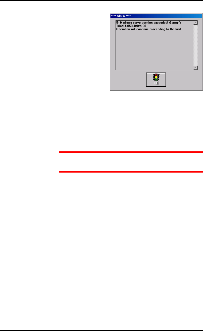
1b) A message similar to Figure 3-63 is displayed.
Operation • Administrator Functions
3—46 PS288 Owner’s Manual
Figure 3-63—Alarm message
1c) Write down the axis (in this case, Y-axis), whether the minimum or
maximum position has been exceeded (in this case, the minimum posi-
tion), and the “Tried” and “Limit” values (in this case, Tried = 4.059
and Limit = 4.08).
1d) Click OK.
2. Enter Service Mode—
CAUTION: Service Mode allows changes that could make the
PS288 inoperable. Do not make changes you are not sure about;
contact Data I/O Customer Support.
2a) Exit AH500 and return to the TaskLink Task/Kit Manager window.
2b) In the Task/Kit Manager window, re-select the Task and click Run.
2c) When the AH500 main screen opens, double-click the “PS Series” area
(see Figure 3-64). This places the AH500 software in Service Mode.