PS288_OwnersMnl_PriorTo2009 - 第116页
Operation • Administrato r Functions 3—56 PS288 Owner’s Manual Figur e 3-74—Selecting the laser marking file 3. Format— 3a) Click Drawing in t he right-hand side of the Properti es window . 3b) Click the Format tab. Figu…
Operation • Administrator Functions
PS288 Owner’s Manual 3—55
For complete instructions on creating a data file from a master device, see
TaskLink online Help.
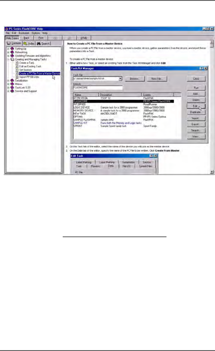
Figure 3-73—Procedure for creating PC file from master device
(Optional) Create a Laser Marking File
Laser graphics used to mark devices are generated using the WinMark Pro
software on the Laser Computer. Any style of marking (whether text-based,
graphic-based, or both) can be generated and used for marking devices. The
only limitation is the size of the device to be marked.
Creating an Image File for the Laser System
To create an image file for the laser system to use in laser marking devices:
1. Prepare the system—
1a) Select the Laser Computer. Copy and paste Template.mkh to create
Copy of Template.mkh.
1b) Rename Copy of Template.mkh to the name you gave the laser marking
(drawing) file in the job creation process, e.g. Ver7.mkh.
1c) Start WinMark Pro by double-clicking the WinMark icon on the desk-
top.
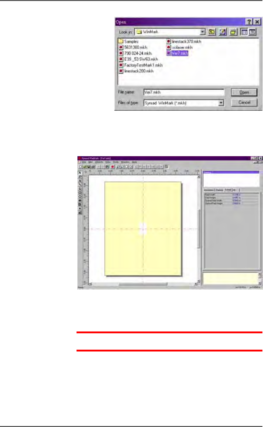
2. Load the file—
2a) From the menu at the top of the window, select File > Load.
2b) Select your laser marking file from the list that appears, or navigate to
the location and select the file.
2c) Click Open to load the file.
Operation • Administrator Functions
3—56 PS288 Owner’s Manual
Figure 3-74—Selecting the laser marking file
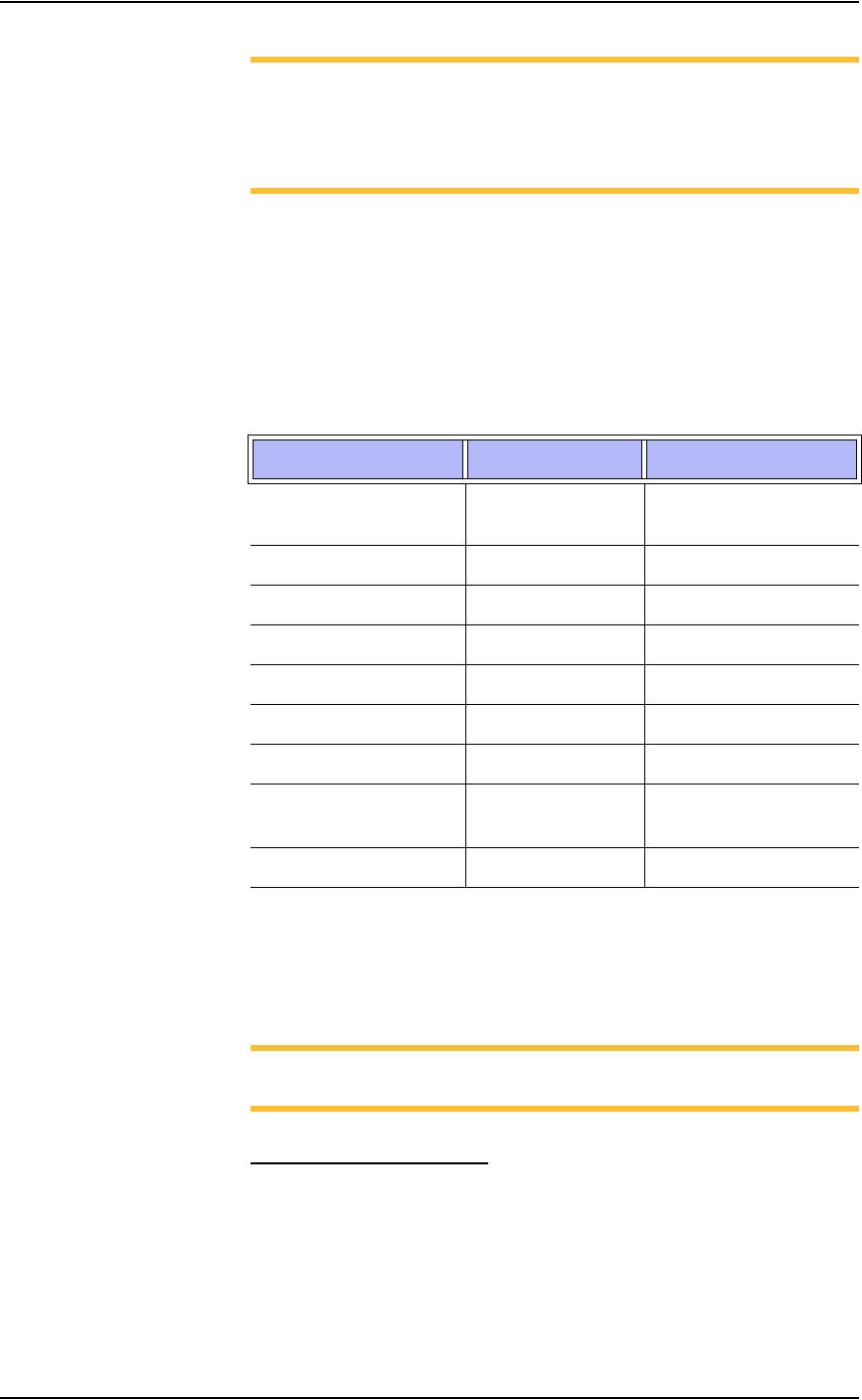
3. Format—
3a) Click Drawing in the right-hand side of the Properties window.
3b) Click the Format tab.
Figure 3-75— Format tab
3c) On the Format tab, set the Optimal Field Width and Optimal Field
Height to the approximate height and width of the device to be marked.
CAUTION: Do NOT change values in the Automation tab. These
values are set in Template.mkh.
4. Create text—
4a) On the vertical tool bar on the left side of the window, select the Text
tool (the button with the letter A on it).
4b) Click the mouse anywhere in the drawing area.
4c) Type the desired text.
Operation • Administrator Functions
PS288 Owner’s Manual 3—57
NOTE: The center of the drawing area is the center of the device to
be marked and is indicated by the red cross hairs. Ensure that the
graphics and text fit onto the surface of the device to be marked.
Use the rulers above and to the left of the drawing area as guides to
marking placement.
4d) Save the file by selecting File > Save from the menu at the top of the
page.
4e) Exit WinMark Pro by selecting File > Exit.
Default Settings in Template.mkh
When creating or editing text, use Stroke fonts. These fonts are drawn and
marked on the devices very quickly using point-to-point vectors. If you
choose True Type fonts instead of Stroke fonts, marking time increases.
Figure 3-76—Template.mkh settings
The three most important settings are Velocity, Power and Resolution. These
three settings, plus object delays on the Marking tab, are the primary factors
that determine the speed and quality of the laser mark on devices.
NOTE: For more information, refer to the manual that came with
your marking system.
Edit Text in an Image File
If an image file already exists and you wish to edit the text:
1. Prepare the system—
1a) Double-click the WinMark icon on the desktop.
1b) From the menu at the top of the window, select File > Load.
1c) Select your laser marking file from the list that appears, or navigate to
the location and select the file.
Setting Default Value Range
Velocity 30 ips (in./sec) Range 0.01 to 240 ips
(0.25 to 6,096 mm/sec)
Power 60% Range 0 to 100%
Resolution 600 dpi 200 to 1000 dpi
Pline Start Delay 100 secs 0 to 80,000 secs
Pline End Delay 450 secs 0 to 80,000 secs
Interseg Delay 350 secs 0 to 80,000 secs
Off Vector Delay 300 secs 0 to 80,000 secs
Off Vector Velocity 75 ips
(1,905 mm/sec)
0 to 600 ips
Off Vector Resolution 300 dpi 0 to 600 dpi