PS288_OwnersMnl_PriorTo2009 - 第122页
Operation • Administrato r Functions 3—62 PS288 Owner’s Manual W ARNING: Do not perform any of the follow ing steps if the laser safety shields have been removed . Extreme burns can occur to anyone in the area of the las…
Operation • Administrator Functions
PS288 Owner’s Manual 3—61
These tests will verify the proper operation of the laser marking system:
1. Prepare the system—
1a) Start the AH500 software.
1b) From the AH500 Setup window, click System.
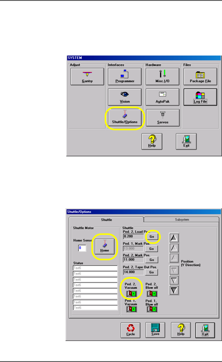
1c) From the System window, select Shuttle/Options.
Figure 3-82—Select Shuttle/Options
2. Shuttle/Options window—
2a) On the Shuttle/Options window, click Home.
2b) Click Go next to Ped.2 Load Pos. to move the laser marking shuttle to
the front of the marking assembly.
2c) Click the Ped. 2 Vacuum switch to the ON position.
Figure 3-83—Shuttle tab

Operation • Administrator Functions
3—62 PS288 Owner’s Manual
WARNING: Do not perform any of the following steps if the laser
safety shields have been removed. Extreme burns can occur to
anyone in the area of the laser if proper safety equipment is not in
place. If these procedures fail, contact Data I/O Customer Sup-
port to place a service call.
2d) Place a device to be marked on marking Pedestal 2, ensuring that it is
centered.
2e) Click Go next to Ped. 2 Mark Pos. to move the laser marking shuttle
to the marking position.
CAUTION: Never fire the laser without a device on the transport
pedestal. Damage to the pedestal O-rings can result.
2f) Select the Subsystem tab.
2g) Click Laser Marker to fire the laser.
2h) When the Done Marking message appears, click the Shuttle tab.
2i) On the Shuttle tab, click Go next to Ped. 2 Load Pos. to move the laser
shuttle to the front of the marking assembly.
3. Verify marking graphic—
3a) Verify that the marking graphic is centered on the device.
3b) If the graphic is not centered, adjust the value in the Ped. 2 Mark Pos.
field until properly centered.
NOTE: Manually placing the device on the transport pedestal will
not be as accurate as allowing the PNP head to place the device.
Manual placement should only be used as a rough alignment when
necessary. Check the laser marking on the devices after the PNP
head has had the opportunity to place them. Make fine adjustments
to the marking position measurements at this time.
4. Troubleshooting—
If the device is not marked, perform the following:
4a) Lay a sheet of paper in the laser bay over the pedestals and fire the
laser.
4b) If the image appears, move the pedestal to center the marking on the
device.
4c) If no image appears, verify power is applied to the laser marking
assembly and that it is turned on.
4d) If all appears correct, contact Data I/O Customer Support for further
assistance.
Operation • Administrator Functions
PS288 Owner’s Manual 3—63
(Optional) Create a Label Printer File
If devices are to be labeled using the optional label printing system, a label
printer file must be created. Follow these steps to create a label printer file.
1. Prepare the system—
Open the label printing software by clicking the shortcut on the Han-
dler Computer desktop or by navigating to and double-clicking
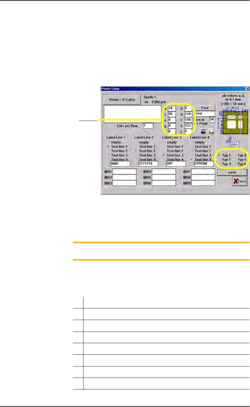
MRPRT.exe. The Printer Setup displays label printing parameters. See
Figure 3-84.
Figure 3-84—Label printing parameters window
2. Select label type—
Select the label type to use when this job is run.The MRPRT software
allows up to six sizes of labels called “types.”
NOTE: Each label type has different values in a to j. All values are
in millimeters.
3. Set a to j values—
Enter the values for fields a to j. See Figure 3-85 for an explanation of
what each value represents.
Meaning/Description
a The offset in X (left to right) of the print from the edge of the label
b The offset in Y (top to bottom) of the print from the edge of the label
c The label size in the X
d The label size in the Y (must be less than value for f)
e This is not used on the PS288 and should be set to 0
f The distance from the front of the label to front edge of the next label
g Rotation (not yet implemented)
Fields a-j