PS288_OwnersMnl_PriorTo2009 - 第126页
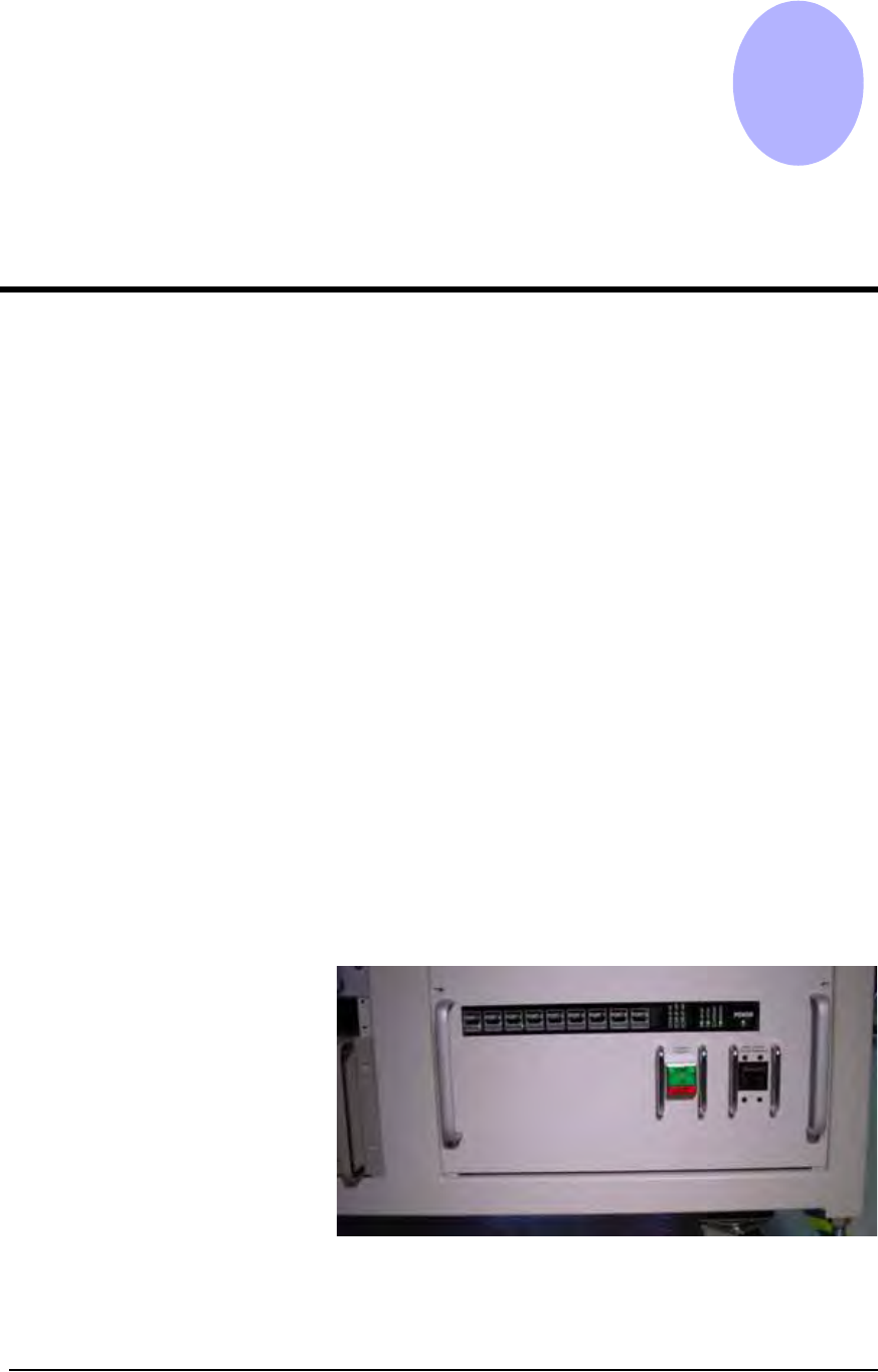
System Theory • FlashCORE Programmer 4—2 PS288 Owner’s Manual The I/O Controller also pr ovides an interface for all sensor systems, several visual indicators, and power and contro l of other systems throughout th e PS28…
PS288 Owner’s Manual 4—1
Chapter
4
4System Theory
The PS288 consists of various electrical and mechanical systems which pro-
vide facilities for—or perform a portion of—the overall operation of the
machine. Their operation and relationship with the other components of the
system are described in this chapter.
Main Power
System
The main power system provides primary and generated voltages for use
within the PS288. Input power is received from the input panel on the rear of
the machine. It is a 208–240 VAC, 50/60 Hz, 30A circuit.
Circuit Breakers
208–240 VAC is provided to the programmer power supplies, gantry servo
motor amplifiers, and the I/O Controller. The two circuit breakers on the
input panel provide circuit protection for the main power input and the gan-
try servo amplifiers.
I/O Controller
The I/O Controller provides 115 VAC, 60 Hz, for all other systems in the
PS288 including, but not limited to, the Handler Computer, video monitor,
and programmer power supplies. Additionally, the I/O Controller provides a
power-on control signal to the servo motor power contactor, allowing the
208–240 VAC to be applied to the gantry’s X and Y servo motor amplifiers
and two low voltage systems used for sensor power and PNP head motor
drivers. See Figure 4-1.
Figure 4-1—I/O Controller
System Theory • FlashCORE Programmer
4—2 PS288 Owner’s Manual
The I/O Controller also provides an interface for all sensor systems, several
visual indicators, and power and control of other systems throughout the
PS288. Sensor conditions are reported back to the Handler Computer
through a series of connections on the rear of the I/O Controller. Connections
supported by the I/O Controller include:
• Air pressure sensors
• Light tower
• Tube vibration assemblies
• Component position optics
• Vacuum and pressure control solenoids and sensors
• Safety shield interlocks
• Tape output control and associated sensors
• Power contactor for the laser marking stage
• Label and laser marking system controls and associated sensors
• Additional connectivity for future options
For a listing of status indicator lights on the I/O Controller, see Appendix A,
“I/O Controller LED Status.”
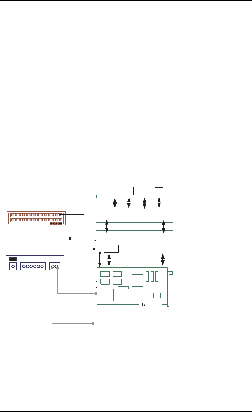
FlashCORE
Programmer
FlashCORE programmer structure is shown in Figure 4-2:
Figure 4-2—Internal structure of FlashCORE programmer
Controller / CPU
RPX Lite
DW or DW-LGMEM
1
2 3
4
Backplane PCB
Waveform PCB
CPLD
FPGA
J3
J4
RJ45
P10
MON PM3
Socket Adapter PCB
ETH
PE3
MPC850SR PowerPC
FdrRoot\Admin.txt
FdrRoot\FdrCfg.txt
FdrRoot\Algs\2711410c.elf
FdrRoot\Algs\HWData_C.elf
FdrRoot\Jobs\<job_name>\FootNote.txt
FdrRoot\Jobs\<job_name>\JobParms.txt
FdrRoot\Jobs\<job_name>\SectProt.txt
FdrRoot\System\DiagLog.txt
FdrRoot\System\ErrOut.txt
FdrRoot\System\EventLog.txt
FdrRoot\System\FdrStat.txt
FdrRoot\System\
NetWork.txt
Programmer IP=139.138.240.4
Subnet Mask=255.255.255.0
Default Gateway=139.138.240.253
Day and Time Server IP=192.169.1.7
PC Port Number=0
Programmer Port Number=7527
Programmer Name=FC 4
SN Server Port Number=7500
SN Server IP=0.0.0.0
FdrRoot\Update\Boot.bin
FdrRoot\Update\HWData_C.elf
FdrRoot\Update\SysFlash.bin
Files on
PCMCIA Card in FlashCORE
J3
Power
+5V(1,2,3,4) GND(5,6,7,8)
+24V(9,10) +12V (11) -12V(12)
Power Supply
one for 2 FlashCORE Programmers
16-port Network Hub
To / from other FC programmers
To 2nd FC programmer

System Theory • FlashCORE Programmer
PS288 Owner’s Manual 4—3
FlashCORE programmers on the PS288 are made up of the following com-
ponents:
CPU - PowerPC Controller Board (RPX-Lite)
The PowerPC Controller Board is based on MCP850 PowerPC CPU and
includes many hardware elements, like 10 Base-t Ethernet port and a
PCMCIA interface.
It has a memory controller that allows the device programming algorithm to
control the bus cycle timing for the memory range used for programming.
The onboard I2C bus is used to address a serial EEPROM on the adapter
board of the programmer to collect statistics on a given socket. The I2C bus
is also used on the RPX Lite Board to address the temperature and thermal
monitor (STTM) and another onboard serial EEPROM used for RPX config-
uration storage.
Waveform Board
The core of the FlashCORE programmer design, the Waveform Board inter-
faces to the PowerPC Controller Board with two programmable logic
devices: a CPLD (non-volatile) and a FPGA (volatile). These two logic
devices make up the basic programmer control circuitry. The CPLD contains
logic to control the communications interfaces as well as the analog controls
of the programmer and configuration of the volatile FPGA. The FPGA is
used to route address, data and control signals from the PowerPC to the
devices in socket, and provide Device Insertion, V
PP
waveform generation,
and Self-test circuit control logic.
Backplane Board
The Backplane Board is a connection scheme to connect the Waveform
Board to the Socket Adapter board. In addition to supplying connections
between the two boards, it also supplies the circuitry for address line buffer-
ing to isolate each device so that a failing part cannot affect non-failing
devices and power and ground switching relays.
Socket Adapter Board
The Socket Adapter Board connects to the Backplane Board to supply the
electrical connections for programming to the individual sockets. It also con-
tains a 10 bit ID bus used to identify the adapter installed. A small EEPROM
exists on this board for maintaining socket cycle counts for this physical
adapter. By putting this EEPROM on the adapter itself, the socket cycle
counts for a specific Socket Adapter Board can be tracked independent of
the FlashCORE programmer it has been installed on.
In each FlashCORE programmer, there is a PCMCIA card that acts as the
local drive for the FlashCORE programmer. There are various sub-directo-
ries and files on this, as shown in Figure 4-2.
Power to FlashCORE programmers is provided by a universal power supply,
which powers two FlashCORE programmers.