PS288_OwnersMnl_PriorTo2009 - 第13页
Introduction • Subassemblies PS288 Owner’s Manual 1—3 An additional axis, called the R-axis ( theta ), is used to adjust the angular (rotational) positio n of devices by the PNP head. Four Basic Operations The PS288 perf…
Introduction • System Description
1—2 PS288 Owner’s Manual
Specifications
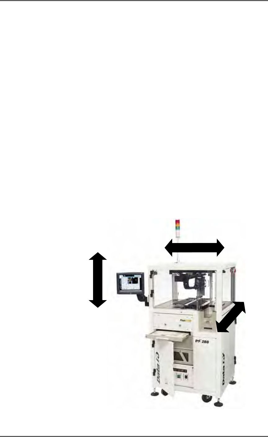
Terms Used to Indicate Direction
The PS288 motion system operates on three primary axes: X, Y, Z. These
axes are used throughout this manual to describe the motion of the various
parts of the system, and are described relative to the front of the PS288.
Figure 1-1—PS288 motion axes
Facilities:
Air Pressure 620-827 kiloPascals (90-120 PSI)
Air Flow 85 liters/minute (3 SCFM)
AC Input Voltage (single phase) 208-240 VAC
AC Input Voltage Frequency 50/60 Hz
AC Input Power (max) 10 A
Dimensions:
Length (including hinges) 900 mm (35 inches)
Width (including hinges) 800 mm (31 inches)
Height 626 mm (64 inches)
Weight 364 kg (800 lbs)
Environment:
Operating Temperature +13 to +30 C (+55 to +86 F)
Humidity (non-condensing) 90%
LEFT
RIGHT
X-AXIS
Z
-
A
X
I
S
(+Z)
(+X)
DOWN
UP
FRONT
Y
-A
XI
S
BACK
(+Y)

Introduction • Subassemblies
PS288 Owner’s Manual 1—3
An additional axis, called the R-axis (theta), is used to adjust the angular
(rotational) position of devices by the PNP head.
Four Basic Operations
The PS288 performs four basic operations when processing devices:
1. Unload devices from the input media—
The pick and place head (PNP head) unloads devices from the input
tube, tray, or tape module. These devices are placed in a programming
socket for programming or on the shuttle pedestal for marking.
2. Program devices—
Devices in the programming sockets go through a series of pre-pro-
gramming tests to make certain they are blank and are correctly
inserted in the sockets. If the tests are successful, the devices are pro-
grammed with the data contained in programmer RAM using an algo-
rithm approved by the semiconductor manufacturer. Data in devices
that pass the programming operation are verified against the RAM data
to ensure that they have been programmed correctly. Testing, program-
ming, and verifying options can be changed from the default settings
using TaskLink software.
3. (Optional) Mark devices—
When marking is selected, devices that pass the programming and veri-
fication operations are moved to a pedestal on the shuttle transfer
assembly, then to the label marker or laser marker where they are
marked for identification.
4. Load devices onto the output media—
Devices are moved by the PNP head from the programming socket or
the marking stage and placed in either trays, tubes, or tape. Devices that
failed the programming operation or subsequent verification are trans-
ported to a dedicated reject tray or other reject module where they are
held for failure analysis or other disposition.
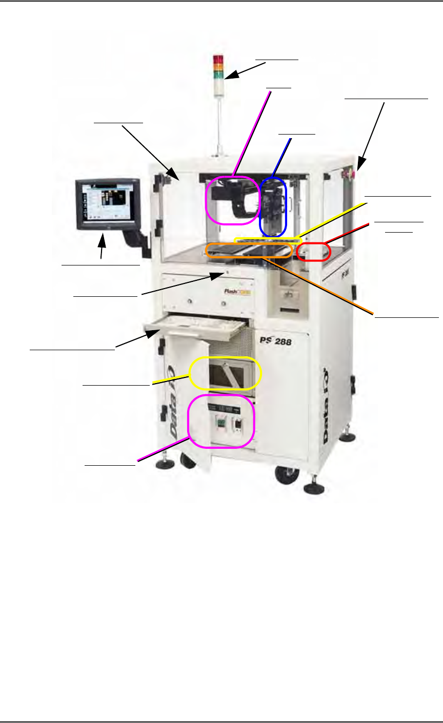
Subassemblies
The PS288 has several subassemblies that work together to provide for
proper operation. Refer to Figure 1-2 for the physical location on the PS288
of the primary subassemblies. (Some of these assemblies are optional and
are not shown in Figure 1-2).
Introduction • Subassemblies
1—4 PS288 Owner’s Manual
Figure 1-2—PS288 primary subassemblies
Light tower—
Allows monitoring the status of the PS288 from a distance while the
system is processing devices. See “Monitor the Light Tower” on page
3-13 for a complete description of light colors and significance.
Gantry—
Travels along X- and Y-axes moving the PNP head to different loca-
tions within the work envelope.
Pick and place head (PNP head)—
The motion system responsible for moving devices to and from their
respective stages within the handler. The PNP head moves devices in
four axes, X, Y, Z and R (also called theta), within the operating enve-
Light Tower
Safety Shields
Touch Screen Monitor
Keyboard and touchpad
Grounding Socket
Vision System
(hidden)
Static Tray Mount
Emergency Stop Button
PNP Head
Handler Computer
I/O Controller
Gantry
FlashCORE Quad