PS288_OwnersMnl_PriorTo2009 - 第148页
Maintenance • Preventive Maintenance PS288 Owner’s Manual 5—13 Figur e 5-7—Z-axis and R-axis servo motor amps 2. Check all wiring harness connections— 2a) Check connections for the Z-ax is and R-axis servo motor amps. 2b…
Maintenance • Preventive Maintenance
5—12 PS288 Owner’s Manual
NOTE: For systems with a tape output system, there is an addi-
tional vacuum generator on the tape output PNP head. Follow the
procedure described above to check and replace if necessary.
Clean Automatic Tray Feeder
1. Conveyor belts and tray platform—
Clean conveyor belts with dry compressed air or dry, lint-free cloth.
Clean the tray platform with lint-free cloth and isopropyl alcohol.
2. Pinch roller—
Check the urethane pinch roller attached to the tray clamping mecha-
nism for signs of wear or damage. Replace if necessary.
Procedures Performed Every Three Months
Replacing a Worn Shuttle Belt
WARNING: Electric shock hazard. Shut down the PS288 (see
“Shut Down the System” on page 3-12) and turn off the main
power switch before removing any panels.
1. Prepare the system—
1a) Verify that the PS288 is shut down and the main power switch is in the
OFF position.
1b) Remove the upper left Option Bay panel.
2. Motor mount—
2a) Loosen the four motor mounting screws.
2b) Pull the motor all the way forward.
3. Remove belt—
3a) Remove the two Allen bolts from the top of the pedestals.
3b) Remove the belt.
4. Replace belt—
Replace the belt by reversing the above steps.
PNP Head (Z and R) Motor Amps
WARNING: Electric shock hazard. Shut down the PS288 (see
“Shut Down the System” on page 3-12) and turn off the main
power switch before removing any panels.
1. Prepare the system—
1a) Verify that the PS288 is shut down and the main power switch is in the
OFF position.
1b) Open the right side cabinet door and locate the R-axis and Z-axis servo
motor amps. See Figure 5-7.
Maintenance • Preventive Maintenance
PS288 Owner’s Manual 5—13
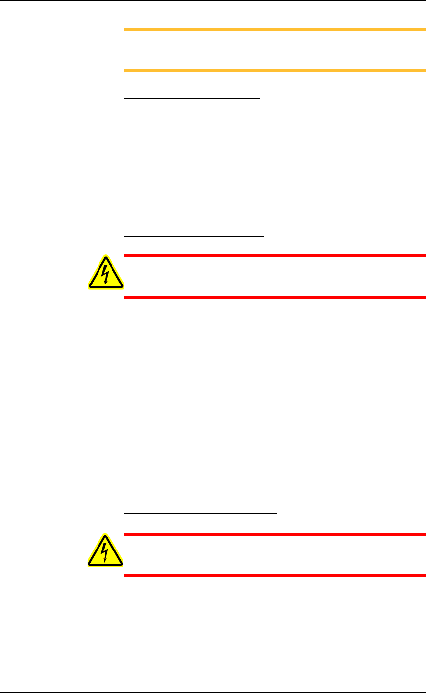
Figure 5-7—Z-axis and R-axis servo motor amps
2. Check all wiring harness connections—
2a) Check connections for the Z-axis and R-axis servo motor amps.
2b) Tighten if necessary.
NOTE: The Z-axis and R-axis servo motor amps are located
directly behind the panel to the left of the gantry servo motor amps.
Some systems may be slightly different.
2c) Reinstall all guards. Close and lock door.
Check the Gantry (X-axis and Y-axis) Servo Motor Amps
WARNING: Electric shock hazard. Shut down the PS288 (see
“Shut Down the System” on page 3-12) and turn off the main
power switch before removing any panels.
1. Prepare the system—
1a) Verify that the PS288 is shut down and the main power switch is in the
OFF position.
1b) Open right side cabinet door and locate the Y-axis and X-axis servo
motor amps. See Figure 5-8.
R-axis
Z-axis
Maintenance • Preventive Maintenance
5—14 PS288 Owner’s Manual
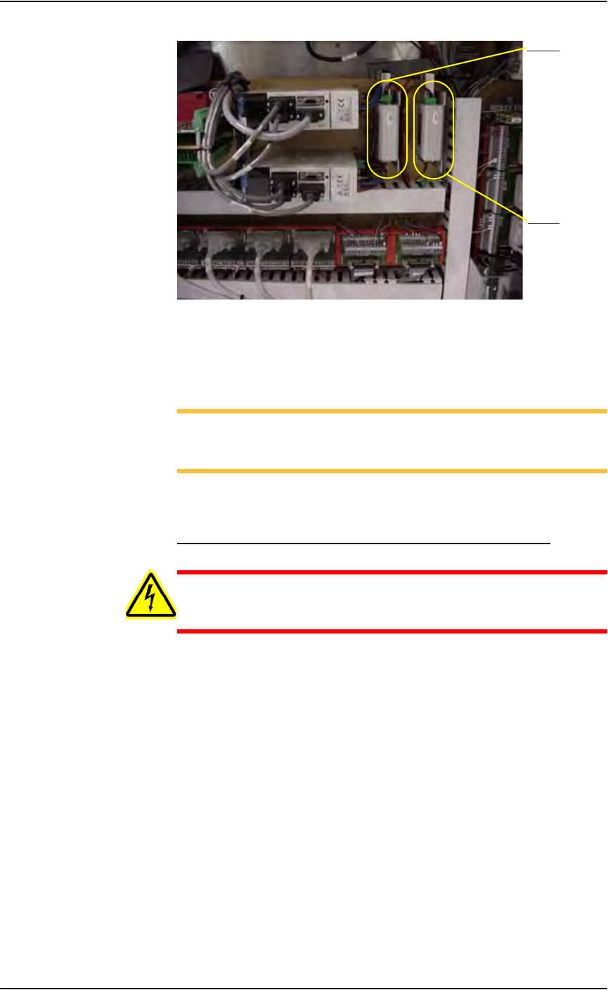
Figure 5-8—Y-axis and X-axis servo motor amps
2. Check wiring harness connections—
2a) Check the wiring harness connections for the X-axis and Y-axis servo
motor amps.
2b) Tighten if necessary.
NOTE: The X-axis and Y-axis servo motor amps are located just
behind the panel and are marked 1Y1 and 1X1.
2c) Reinstall all guards and panels.
Check the Gantry (X and Y) Mounting Bolts
WARNING: Electric shock hazard. Shut down the PS288 (see
“Shut Down the System” on page 3-12) and turn off the main
power switch before removing the lead screw shields.
1. Prepare the system—
1a) Verify that the PS288 is shut down and the main power switch is in the
OFF position.
1b) Remove the four bolts that hold the two lead screw shields to the gantry
rails.
1c) Remove the shields.
2. Check X-axis lead screw rail—
From the bottom side of the X-axis lead screw rail, check and tighten
the mounting bolts located on each end of the rail.
3. Check Y-axis lead screw rail—
From the bottom side of the Y-axis lead screw rail in the center of the
rail, check and tighten the four mounting bolts.
4. Reinstall—
Reinstall the two lead screw shields.
Y- ax i s
X-axis