PS288_OwnersMnl_PriorTo2009 - 第149页
Maintenance • Preventive Maintenance 5—14 PS288 Owner’s Manual Figur e 5-8—Y -axis and X-axis servo motor amps 2. Check wiring ha rness connections— 2a) Check the wiring harness connections for the X-axis and Y -axis ser…
Maintenance • Preventive Maintenance
PS288 Owner’s Manual 5—13
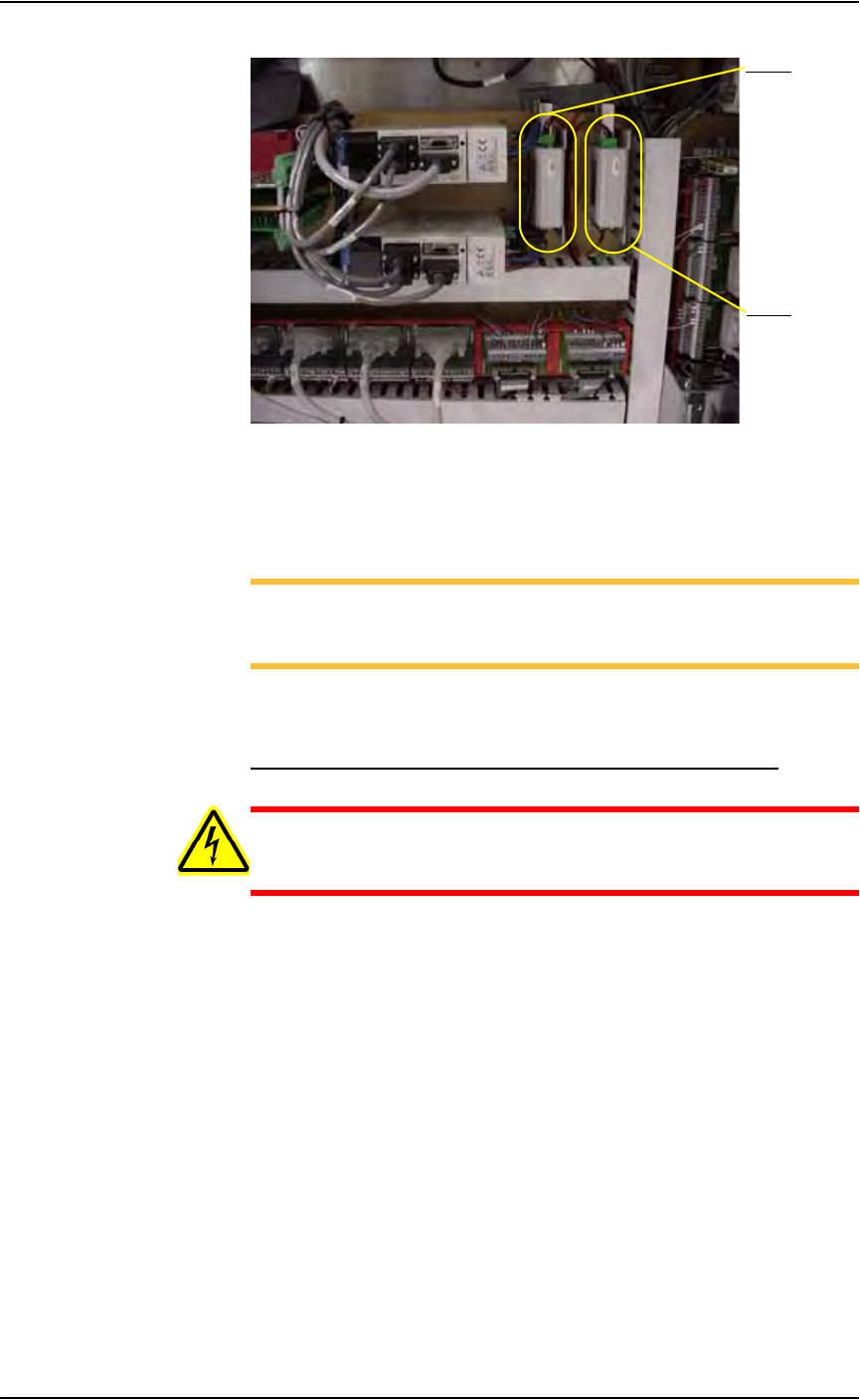
Figure 5-7—Z-axis and R-axis servo motor amps
2. Check all wiring harness connections—
2a) Check connections for the Z-axis and R-axis servo motor amps.
2b) Tighten if necessary.
NOTE: The Z-axis and R-axis servo motor amps are located
directly behind the panel to the left of the gantry servo motor amps.
Some systems may be slightly different.
2c) Reinstall all guards. Close and lock door.
Check the Gantry (X-axis and Y-axis) Servo Motor Amps
WARNING: Electric shock hazard. Shut down the PS288 (see
“Shut Down the System” on page 3-12) and turn off the main
power switch before removing any panels.
1. Prepare the system—
1a) Verify that the PS288 is shut down and the main power switch is in the
OFF position.
1b) Open right side cabinet door and locate the Y-axis and X-axis servo
motor amps. See Figure 5-8.
R-axis
Z-axis
Maintenance • Preventive Maintenance
5—14 PS288 Owner’s Manual
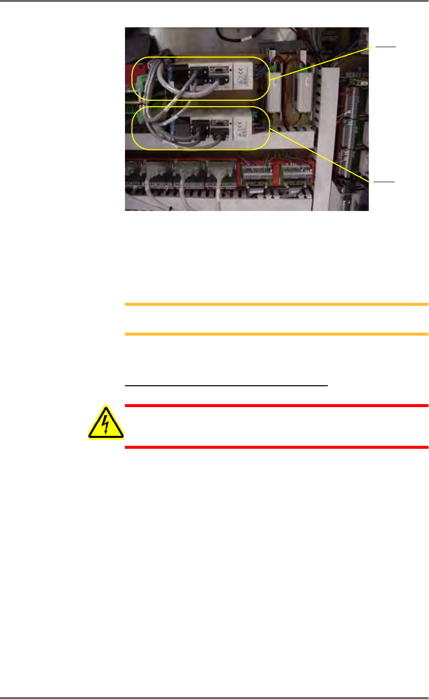
Figure 5-8—Y-axis and X-axis servo motor amps
2. Check wiring harness connections—
2a) Check the wiring harness connections for the X-axis and Y-axis servo
motor amps.
2b) Tighten if necessary.
NOTE: The X-axis and Y-axis servo motor amps are located just
behind the panel and are marked 1Y1 and 1X1.
2c) Reinstall all guards and panels.
Check the Gantry (X and Y) Mounting Bolts
WARNING: Electric shock hazard. Shut down the PS288 (see
“Shut Down the System” on page 3-12) and turn off the main
power switch before removing the lead screw shields.
1. Prepare the system—
1a) Verify that the PS288 is shut down and the main power switch is in the
OFF position.
1b) Remove the four bolts that hold the two lead screw shields to the gantry
rails.
1c) Remove the shields.
2. Check X-axis lead screw rail—
From the bottom side of the X-axis lead screw rail, check and tighten
the mounting bolts located on each end of the rail.
3. Check Y-axis lead screw rail—
From the bottom side of the Y-axis lead screw rail in the center of the
rail, check and tighten the four mounting bolts.
4. Reinstall—
Reinstall the two lead screw shields.
Y- ax i s
X-axis
Maintenance • Preventive Maintenance
PS288 Owner’s Manual 5—15
Check the Tray-Present Sensors
1. Check fiber optics—
Check that the fiber optics are illuminated at each tray position.
2. Check sensor mounting set screws—
Check and if necessary tighten each sensor mounting set screw.
3. Reset sensor if position has changed—
3a) If the sensor position has changed, loosen the set screws.
3b) Insert a tray into the tray holder.
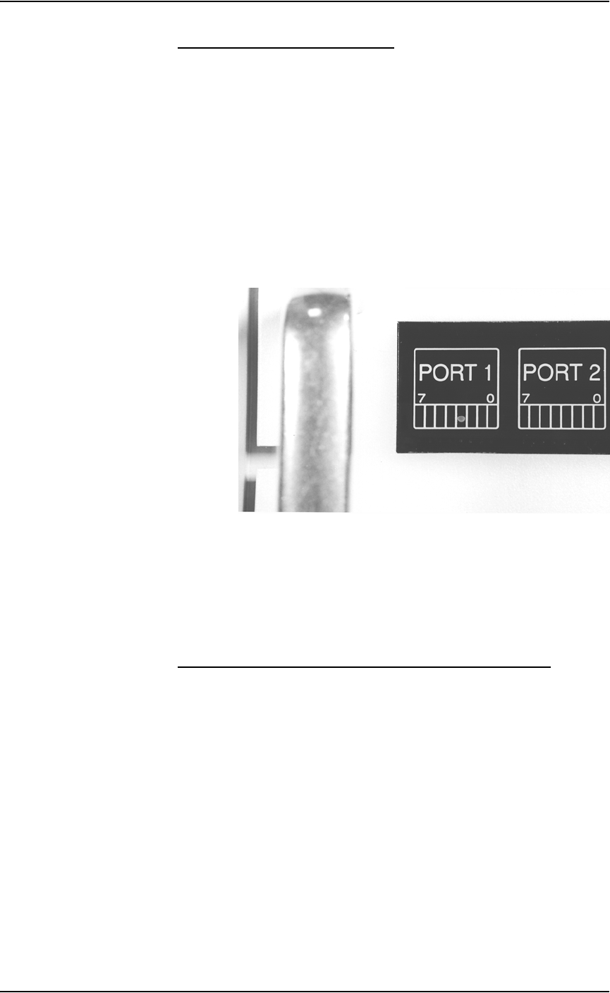
3c) Adjust the sensor so that I/O Controller LED Port 1, Bit 3 is on when
Tray 1 is inserted. See Figure 5-9.
3d) Adjust the sensor so that I/O Controller LED Port 1, Bit 4 is on when
Tray 2 is inserted.
Figure 5-9—I/O Controller LED showing Port 1, Bit 3 is on
3e) Tighten the set screws.
3f) Remove the tray and check that the LED is off.
Procedures Performed Every Six Months
Check the PNP Head and PNP Gantry Wiring Harnesses
1. Check—
1a) Check and if necessary tighten the mounting screws of the PNP head
wiring harness. See Figure 5-10.