PS288_OwnersMnl_PriorTo2009 - 第15页
Introduction • Subassemblies PS288 Owner’s Manual 1—5 lope. A computerized vi sion system allows the PNP head to make adjustments for very accurate device placement. The PNP head uses different sized probe tips to accomm…
Introduction • Subassemblies
1—4 PS288 Owner’s Manual
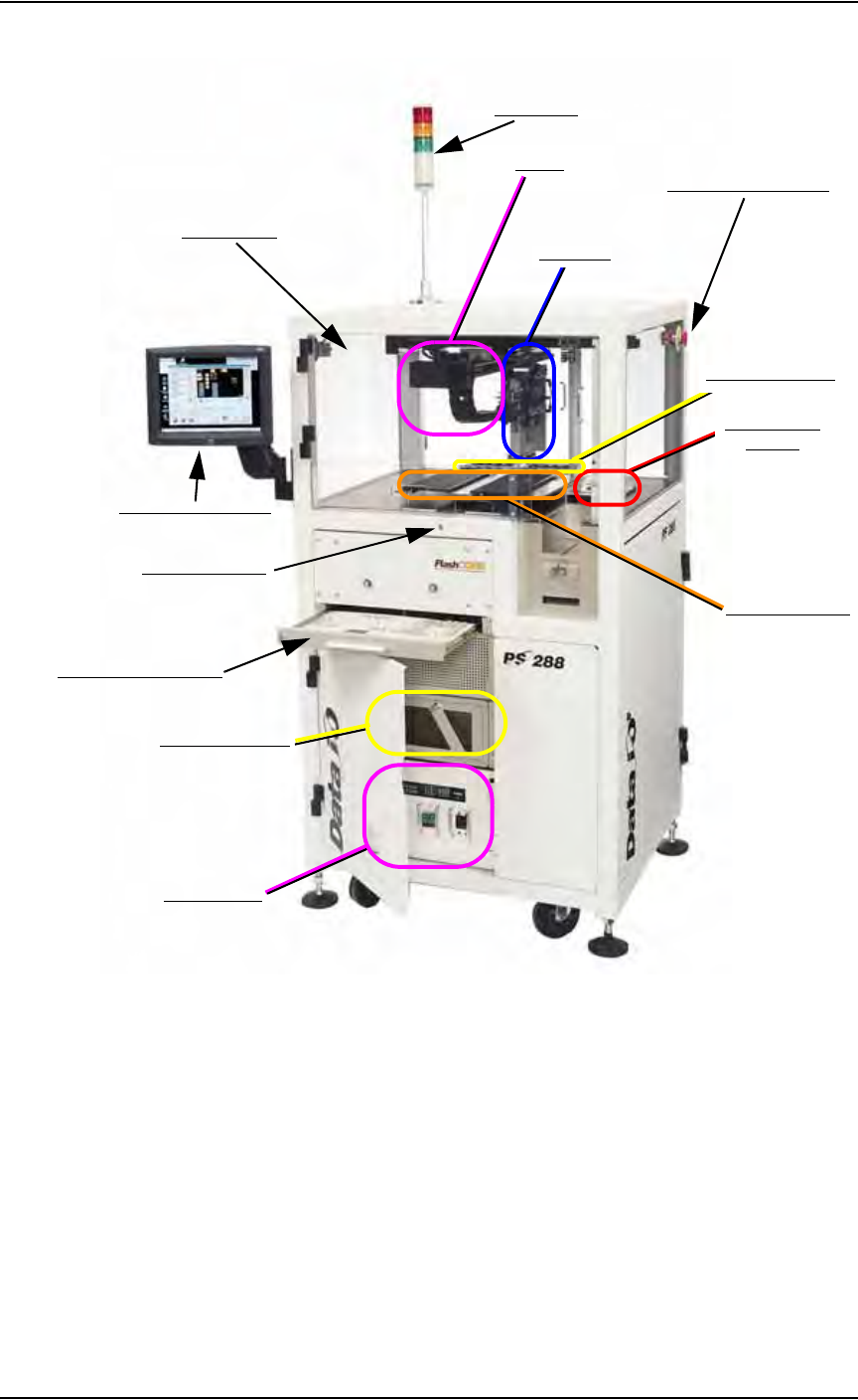
Figure 1-2—PS288 primary subassemblies
Light tower—
Allows monitoring the status of the PS288 from a distance while the
system is processing devices. See “Monitor the Light Tower” on page
3-13 for a complete description of light colors and significance.
Gantry—
Travels along X- and Y-axes moving the PNP head to different loca-
tions within the work envelope.
Pick and place head (PNP head)—
The motion system responsible for moving devices to and from their
respective stages within the handler. The PNP head moves devices in
four axes, X, Y, Z and R (also called theta), within the operating enve-
Light Tower
Safety Shields
Touch Screen Monitor
Keyboard and touchpad
Grounding Socket
Vision System
(hidden)
Static Tray Mount
Emergency Stop Button
PNP Head
Handler Computer
I/O Controller
Gantry
FlashCORE Quad
Introduction • Subassemblies
PS288 Owner’s Manual 1—5
lope. A computerized vision system allows the PNP head to make
adjustments for very accurate device placement.
The PNP head uses different sized probe tips to accommodate the great
number of device types that are available. During operation, a vacuum
is switched on as the probe tip is lowered toward the device. A vacuum
sensor is used to detect when the probe tip touches the device. The PNP
head then picks up the device and moves it to the camera where it com-
pares the device position on the probe tip to a digital image of a known
good position. It can then correct for probe misalignments on the X, Y,
and R axes (up to 30°) before the device is placed in the programming
socket.
Once corrections are made, the PNP head moves the device to the drop
location, the probe tip is lowered, and the vacuum is turned off. The
drop position of the probe tip is slightly higher than the pickup posi-
tion, as a blow-off, a small amount of positive-pressure air, is applied to
break the vacuum seal. The short drop from the probe tip to the pro-
gramming socket or output media prevents fine pitched leads from
being damaged by excessive pressure.
WARNING: The gantry system and associated components move
with great speed and force, and have the potential to cause great
bodily harm. Do not bypass the safety interlocks or operate the
PS288 with the safety shields open or removed.
Emergency stop (E-Stop) buttons—
Two E-Stop buttons (on either side of the PS288 near the top) are used
to stop motion of the gantry and PNP head in case of an emergency.
When an E-Stop button is pressed, the gantry and PNP head stop mov-
ing immediately.
WARNING: Pressing an E-Stop button stops motion of the gan-
try and PNP head only. It does not remove power from the PS288
or the Option Bay (if installed).
Quad Programmer Assembly —
A Quad assembly containing four FlashCORE programmers that
accept Socket Adapters with 1 to 4 sockets each, for a total of up to 16
programming sockets.
Vision system—
The camera and associated components of the vision system are used to
verify proper alignment of devices removed from the input media
before inserting them into the programming sockets. Misalignments are
corrected before placing the device in the programming socket or
marking pedestal.

Introduction • Subassemblies
1—6 PS288 Owner’s Manual
Static tray mount—
Using positioning pins and “L” bracket magnets, holds several differ-
ent tray sizes including JEDEC and non-JEDEC standard trays in posi-
tion for the PNP to pick up devices and return them after processing.
I/O Controller—
Provides 115 VAC for the Handler Computer and associated compo-
nents, as well as the PNP head. Also provides 24VDC for the various
sensor systems throughout the PS288. The I/O Controller provides a
transfer point for all sensor signals within the PS288 and optional
assemblies, and sends the signals to the Handler Computer for process-
ing.
Handler Computer—
The Handler Computer operates using the Microsoft
®
Windows XP
operating system. It hosts TaskLink and AH500 operating software for
the PS288, monitors all sensors, and hosts the vision system.
CAUTION: The PS288 should never have software added unless
instructed to do so by Data I/O Customer Support. Adding software
to the PS288 can cause damage and/or cause the system to operate
improperly. Adding software without specific instruction from
Data I/O Customer Support will void the warranty and may incur
service charges.
Keyboard and touchpad—
Used to set up system operation. Can be used instead of the touch
screen monitor if desired.
Grounding socket—
Used to prevent damage to devices from electrostatic discharge (ESD).
Operators should wear an antistatic wrist strap inserted in the ground-
ing socket.
Touch screen monitor—
Central display mechanism for the PS288, shows system status and
information about programming jobs and vision system. The touch
screen may be used instead of the keyboard and touchpad if desired.
NOTE: Throughout this manual, the term “click” is used to mean
“touch” when using the touch screen monitor.
Safety shields—
Used to protect against personnel and equipment damage when the
PNP head is in motion. Safety interlocks on the safety shields stop
movement of the gantry and PNP head if the shields are opened or
removed while the gantry is in operation.