PS288_OwnersMnl_PriorTo2009 - 第151页
Maintenance • Preventive Maintenance 5—16 PS288 Owner’s Manual Figur e 5-10—PNP head mounting scr ews 1b) Check PNP gantry wiring harness plug conn ections and make sure that they are secure. See Figur e 5-1 1 . Figur e …
Maintenance • Preventive Maintenance
PS288 Owner’s Manual 5—15
Check the Tray-Present Sensors
1. Check fiber optics—
Check that the fiber optics are illuminated at each tray position.
2. Check sensor mounting set screws—
Check and if necessary tighten each sensor mounting set screw.
3. Reset sensor if position has changed—
3a) If the sensor position has changed, loosen the set screws.
3b) Insert a tray into the tray holder.
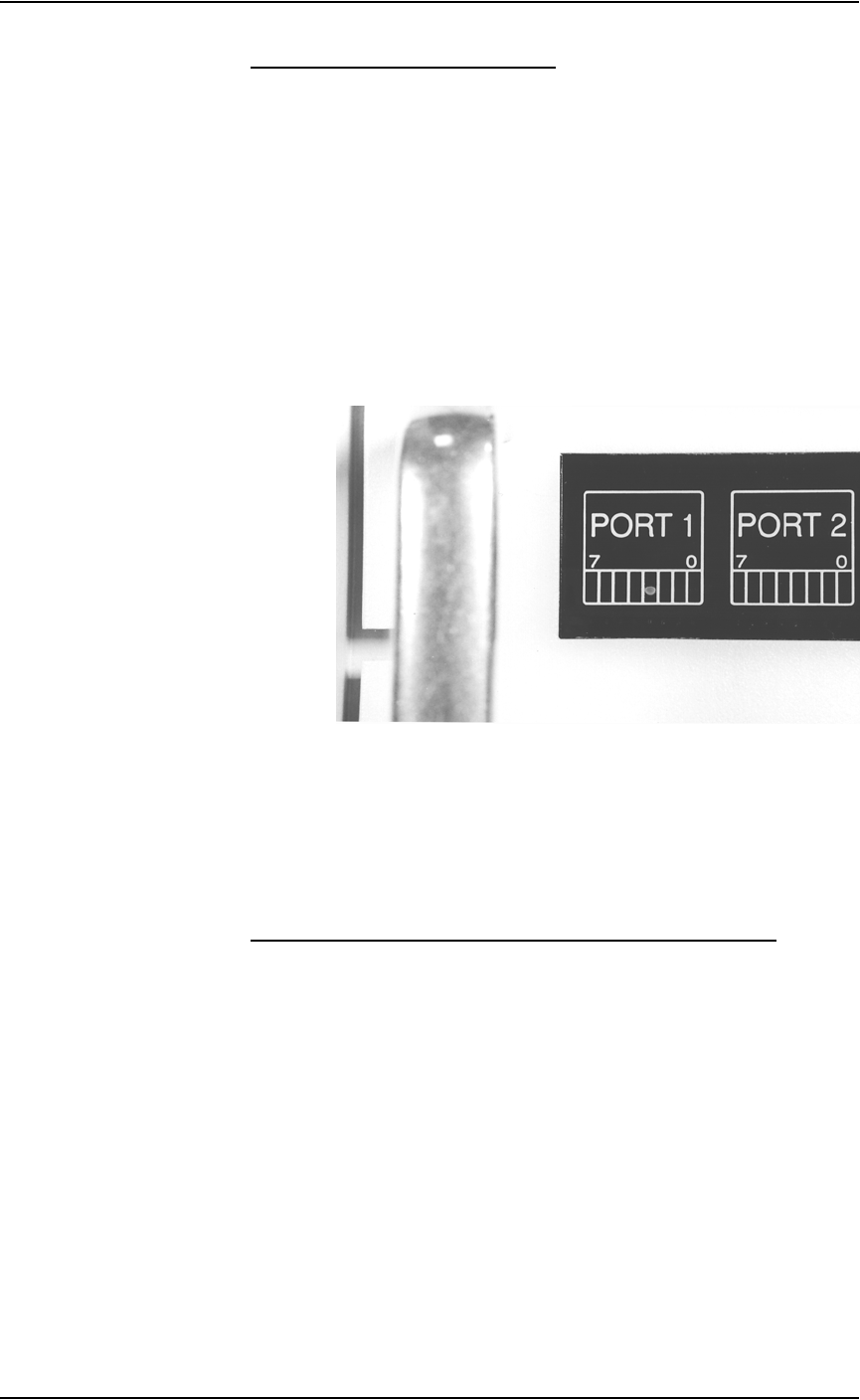
3c) Adjust the sensor so that I/O Controller LED Port 1, Bit 3 is on when
Tray 1 is inserted. See Figure 5-9.
3d) Adjust the sensor so that I/O Controller LED Port 1, Bit 4 is on when
Tray 2 is inserted.
Figure 5-9—I/O Controller LED showing Port 1, Bit 3 is on
3e) Tighten the set screws.
3f) Remove the tray and check that the LED is off.
Procedures Performed Every Six Months
Check the PNP Head and PNP Gantry Wiring Harnesses
1. Check—
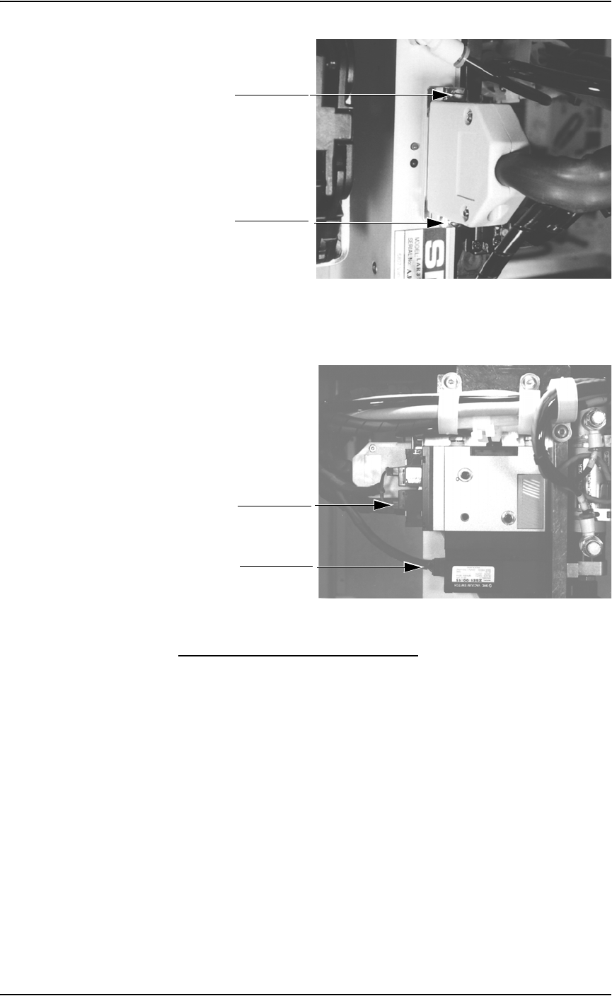
1a) Check and if necessary tighten the mounting screws of the PNP head
wiring harness. See Figure 5-10.
Maintenance • Preventive Maintenance
5—16 PS288 Owner’s Manual
Figure 5-10—PNP head mounting screws
1b) Check PNP gantry wiring harness plug connections and make sure that
they are secure. See Figure 5-11.
Figure 5-11—PNP gantry wiring harness plug connections
Clean and Check the Cable Carriers
1. Clean—
Use dry compressed air to remove all foreign material from the cable
carriers.
2. Check—
2a) Check that the cables are not too loose or too tight. The cables should
be in good condition.
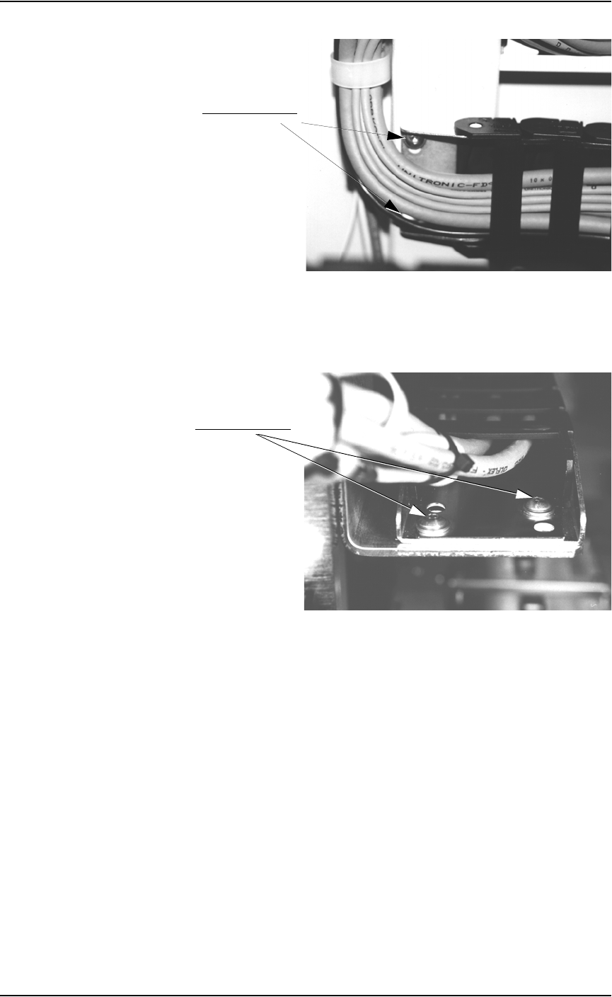
2b) Check the two screws on the upper carrier and tighten if necessary.
See Figure 5-12.
Mounting screw
Mounting screw
Plug connection
Plug connection
Maintenance • Preventive Maintenance
PS288 Owner’s Manual 5—17
Figure 5-12—Upper carrier screw locations (one is hidden in this view)
2c) Check the two screws on the lower carrier and tighten if necessary. See
Figure 5-13.
Figure 5-13—Lower carrier screw locations
2d) Check the four screws on the center carrier and tighten if necessary.
See Figure 5-14.
Upper carrier screws
Lower carrier screws