PS288_OwnersMnl_PriorTo2009 - 第162页
Maintenance • Preventive Maintenance PS288 Owner’s Manual 5—27 5. Remove filters— 5a) Remove all four filt ers and carefully place in the sealable bag. 5b) Pull off the disposable protective gloves and place in the seala…
Maintenance • Preventive Maintenance
5—26 PS288 Owner’s Manual
Figure 5-26—Side laser housing panel screw locations
2. Take safety precautions—
Put on the disposable protective gloves and open the sealable plastic
bag.
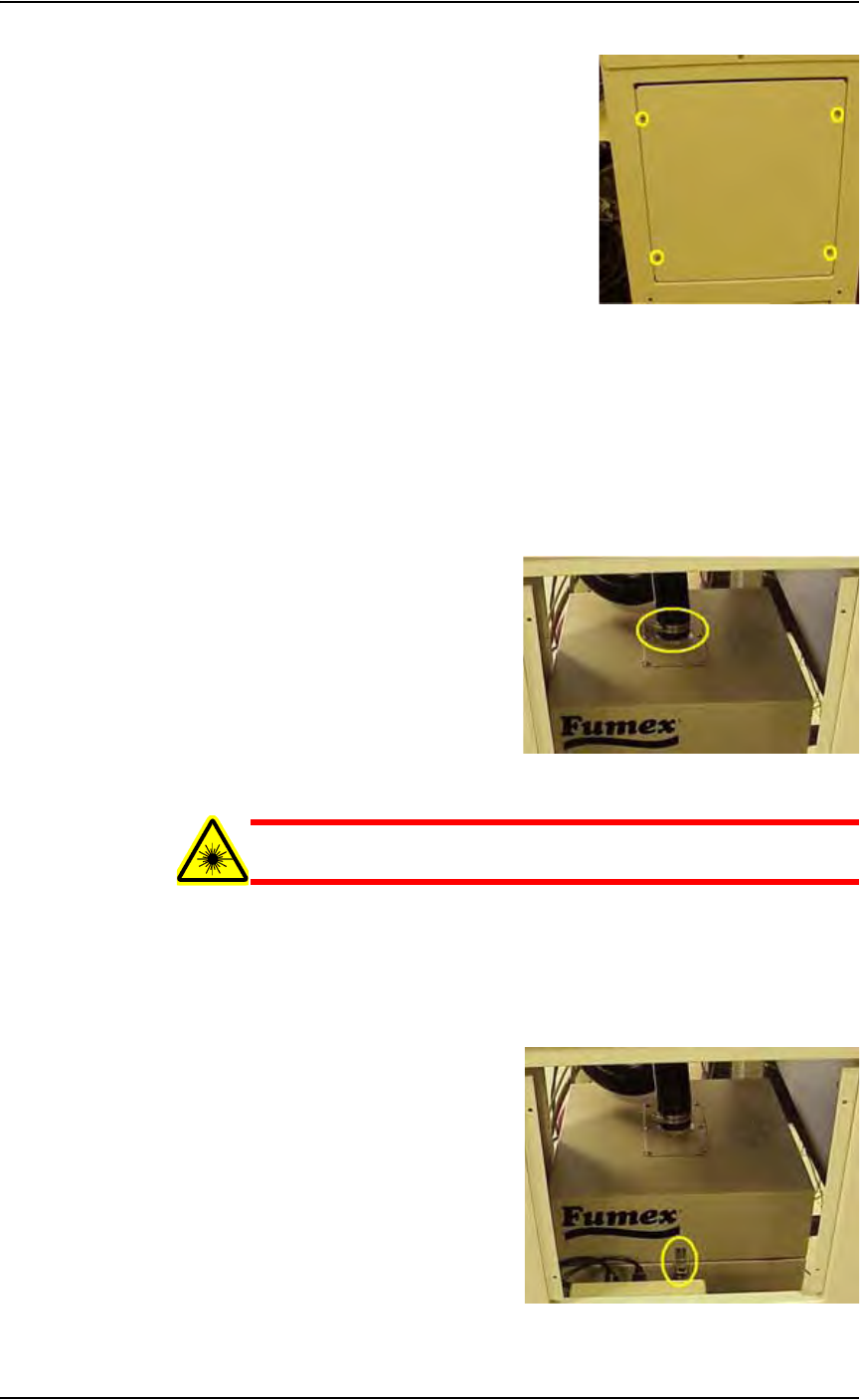
3. Detach vacuum hose—
3a) Loosen the clamp holding the vacuum hose to the extractor top and
detach the vacuum hose from the extractor top. See Figure 5-27.
3b) Carefully set the vacuum hose aside.
Figure 5-27—Vacuum hose clamp
WARNING: Hazardous materials. Do not allow particulate mat-
ter in the vacuum hose to be released into the work environment.
4. Release spring clips—
4a) Release the four spring clips (one on each side) that secure the extrac-
tor top to the filter system. See Figure 5-28 for location of one spring
clip.
4b) Remove the extractor top and set aside.
Figure 5-28—Filter system spring clip

Maintenance • Preventive Maintenance
PS288 Owner’s Manual 5—27
5. Remove filters—
5a) Remove all four filters and carefully place in the sealable bag.
5b) Pull off the disposable protective gloves and place in the sealable bag.
5c) Seal the bag and dispose of as hazardous waste.
WARNING: Numerous government regulations apply to the stor-
age and disposal of hazardous waste. Ensure that contaminated
filters are properly labeled and stored in your hazardous waste
storage area. Also, make sure that they are not stored on your site
longer than government regulations allow (the typical limit is 90
days). Check your government (local, state, and federal) regula-
tions for hazardous waste storage requirements.
6. Replace filters—
6a) Replace the pre-filter with Data I/O Model Name Pre-Filter, Polyes-
ter.
6b) Replace the pleated filter with Data /O Model Name Filter, Panel,
Pleated.
6c) Replace the HEPA filter with Data I/O Model Name Filter, HEPA,
Particle, BD Frame.
6d) Replace the carbon filter with Data I/O Model Name Activated Car-
bon Cell, 3lb NET.
7. Re-install extractor top—
7a) Carefully place the extractor top on the filter system.
7b) Attach the four spring clips that secure the extractor top in place.
8. Re-install vacuum hose—
8a) Carefully attach the vacuum hose to the extractor top.
8b) Tighten the clamp that secures it in place.
9. Re-install panels—
Re-install lower back laser housing panel and side laser housing panel.
Testing and Calibrating FlashCORE Programmers
To optimize programming yields, voltages within the FlashCORE program-
mer need to be calibrated once each year.
You will need:
• Diagnostic Adapter Board (DAB), Data I/O part number 910-2200-003
(or later).
This Diagnostic Adapter Board (DAB) detects and isolates problems related
to FlashCORE programmers containing either RPX-Lite DW or
DW-LGMEM. The DAB tests the Waveform Circuit Board and Backplane
Circuit Board. The DAB can also be used to locate problems that have not
yet shown symptoms.
Data I/O suggests performing the programmer diagnostic test annually. This
DAB requires a minimum firmware version 03.00.00.C.
The DAB performs these nine tests:

Maintenance • Preventive Maintenance
5—28 PS288 Owner’s Manual
1. Bus Test
2. Adapter ID Test
3. LED Driver Test
4. G Node Test
5. Vcc Overcurrent Test
6. Vpp Overcurrent Test
7. I2C Bus Test
8. DAC Calibration Test
9. Gslew Test
To run diagnostic tests on FlashCORE programmer(s):
1. Prepare the system—
1a) Turn the programmer circuit breaker on the rear panel to OFF (down
position).
WARNING: To prevent ESD shock, before you touch the Socket
Adapter, discharge static electricity from yourself by touching a
common ground or an unpainted metal surface. Always wear a
wrist strap containing a 1M-ohm (minimum value) to 10M-ohm
(maximum value) current limiting resistor. Connect the antistatic
wrist strap to the grounding socket on the front of the PS288.
1b) Remove the Socket Adapter and insert the Diagnostic Adapter Board in
the desired programmer, ensuring that it seats correctly on the adapter
pins.
1c) Turn the programmer circuit breaker on the rear panel to ON (up posi-
tion)
2. TaskLink—
2a) Start TaskLink and click the Tools menu.
2b) Under Tools, select "Run Programmer Diagnostics."
2c) On the Diagnostics window, select the programmer with the DAB
installed.
2d) Select Test All.
The pass/fail test results are displayed in TaskLink and are also written to
/fdrroot/system/diaglog.txt and /fdrroot/system/eventlog.txt files on the
PC card of the selected FlashCORE programmer. These files can be viewed
and saved from TaskLink and saved on the Handler Computer.
If any of the tests show Fail in the TaskLink display, contact your nearest
Data I/O Service Center for repair options. To help our service personal
diagnose your problem, please e-mail both the eventlog.txt and diaglog.txt
files.
A sample dialog.txt file is shown here:
Diagnostic Pass #1
Run Vpp Overcurrent test.
DUT 1 G1 Vpp overcurrent is sensed at 57 mA.
DUT 1 G2 Vpp overcurrent is sensed at 57 mA.
DUT 1 G3 Vpp overcurrent is sensed at 57 mA.
DUT 1 G4 Vpp overcurrent is sensed at 57 mA.