PS288_OwnersMnl_PriorTo2009 - 第165页
Maintenance • Adjustments, Calibrations, and Function al Tests 5—30 PS288 Owner’s Manual W ARNING: Electrocution hazard ! T urn off the main power switch before removing any panels. Servicing the PS288 involves a signifi…

Maintenance • Laser Computer
PS288 Owner’s Manual 5—29
DUT 2 G1 Vpp overcurrent is sensed at 57 mA.
DUT 2 G2 Vpp overcurrent is sensed at 57 mA.
DUT 2 G3 Vpp overcurrent is sensed at 57 mA.
DUT 2 G4 Vpp overcurrent is sensed at 57 mA.
Error: DUT 3 G1 Vpp overcurrent is not sensed from 50 mA to 70 mA.
Error: DUT 3 G2 Vpp overcurrent is not sensed from 50 mA to 70 mA.
Error: DUT 3 G3 Vpp overcurrent is not sensed from 50 mA to 70 mA.
Error: DUT 3 G4 Vpp overcurrent is not sensed from 50 mA to 70 mA.
DUT 4 G1 Vpp overcurrent is sensed at 57 mA.
DUT 4 G2 Vpp overcurrent is sensed at 57 mA.
DUT 4 G3 Vpp overcurrent is sensed at 57 mA.
DUT 4 G4 Vpp overcurrent is sensed at 57 mA.
Diagnostics failed
Laser Computer
The Laser Computer is used to laser mark devices. Located in the Option
Bay, the Laser Computer requires no maintenance other than cleaning and
changing the filter. The filter on the Laser Computer should be cleaned every
month and changed every six months. See “Change the Laser Computer Air
Filter” on page 22.
Handler
Computer
Installing AH500 Updates
Periodically you will receive AH500 updates as changes and improvements
are made to the software.
NOTE: AH500 Updates are numbered AH500_XXYY, where XX =
the version number and YY = the minor release number.
To install new AH500 updates on your Handler Computer, insert the update
CD and follow instructions on the Readme.txt file.
Adjustments,
Calibrations,
and Functional
Tests
The PS288 requires periodic adjustments, calibrations, and functional tests
to maintain optimum performance of the sensors, the PNP head system, and
FlashCORE programmers.
WARNING: Blindness hazard! Always wear eye protection when
the laser safety shields are open, such as during service. Direct or
diffuse laser radiation can damage eyes. Goggles must block
10.6 µm, laser radiation. Goggles are designed to protect against
scattered energy, but not against direct viewing of the laser beam
or reflections from other surfaces.
WARNING: Serious burn hazard! Enclose the laser beam path
during service. Direct or diffuse laser radiation can seriously
burn.
Maintenance • Adjustments, Calibrations, and Functional Tests
5—30 PS288 Owner’s Manual
WARNING: Electrocution hazard! Turn off the main power
switch before removing any panels. Servicing the PS288 involves
a significant risk of electric shock.
WARNING: The high speed and force behind a moving gantry
can cause serious bodily injury to anyone working inside the work
envelope. Moving the PNP head must be the responsibility of only
one qualified individual. All other personnel near the system must
stay clear of the work envelope while the gantry is moving.
Adjusting the Vacuum Sensors
NOTE: If you notice consecutive picking errors while program-
ming, before adjusting vacuum sensors complete the Z-Axis adjust-
ment. For instructions on Z-Axis adjustment, see “Teach the
Package File” on page 3-33. If completing the Z-Axis adjustment
does not reduce or eliminate subsequent picking errors, complete
the vacuum sensor adjustments described here.
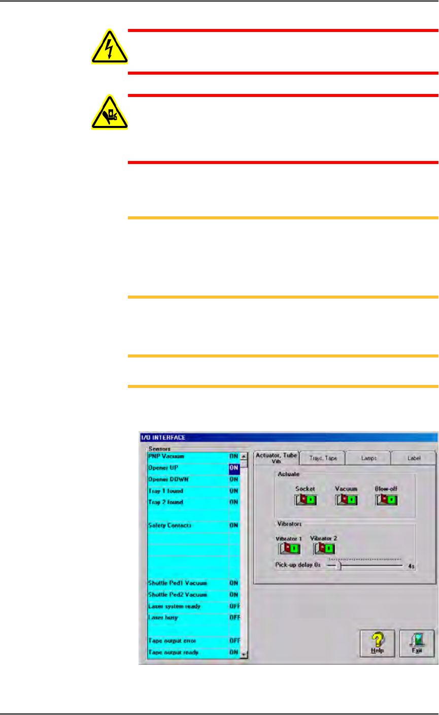
Vacuum sensors on the PS288 are adjustable. The I/O Interface window
displays a list of the sensors in the PS288 and the status of each sensor.
NOTE: The number of sensors on the PS288 depends on the
options installed.
To view the status of sensors in the system, on the AH500 main window
click System, and then click Misc. I/O to open the I/O Interface window.
Figure 5-29—I/O Interface window
Maintenance • Adjustments, Calibrations, and Functional Tests
PS288 Owner’s Manual 5—31
• The PS288 has an adjustable vacuum generator sensor on the PNP
head. See “PNP Head Vacuum Generator Sensor” on page 31
• If the PS288 has the optional label or laser marking system, or the
optional tape output system, there are adjustable vacuum generator sen-
sors for the shuttle transfer system. See “Shuttle Ped 1 and 2 Vacuum
Generator Sensors” on page 32
• If the PS288 has the optional tape output system, there is an adjustable
vacuum generator sensor on the tape output PNP head. See “Tape Out-
put PNP Head Vacuum Generator Sensor” on page 34.
PNP Head Vacuum Generator Sensor
1. Gantry window—
1a) On the Gantry window, move the PNP head to either the Tape or Vision
location.
NOTE: To move the PNP head, on the touch screen place the arrow
over either the Tape or Vision location and right-click the touchpad.
1b) Click the Gantry Vacuum switch to ON.
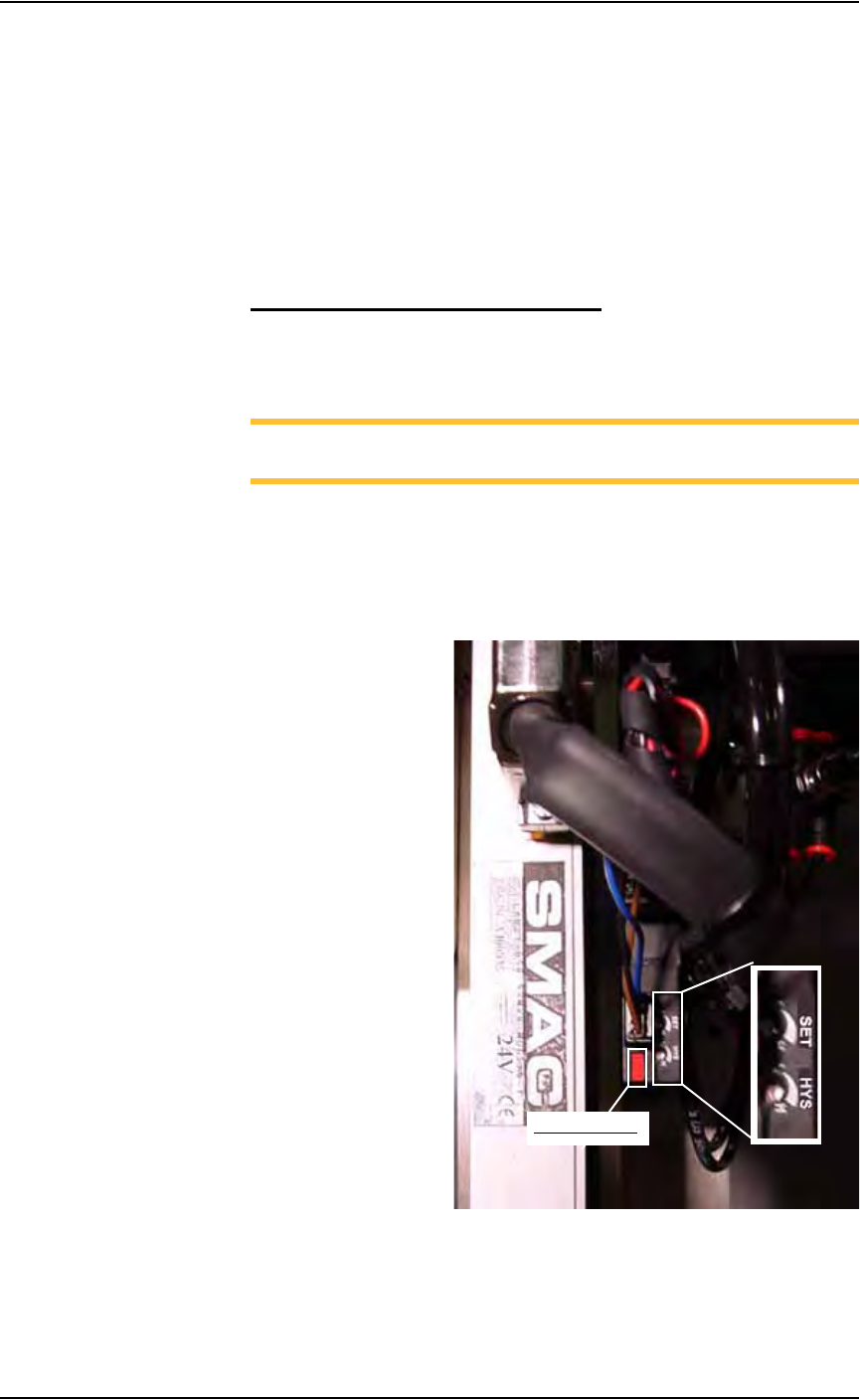
2. Vacuum sensor—
On the vacuum generator sensor, locate the adjustment screws labeled
HYS and SET. Locate the red sensor light. See Figure 5-30.
Figure 5-30—Vacuum sensor light. SET and HYS adjustment screws
Red sensor light