PS288_OwnersMnl_PriorTo2009 - 第166页
Maintenance • Adjustments, Calibrations, and Function al Tests PS288 Owner’s Manual 5—31 • The PS288 has an adjustable vacuum generato r sensor on the PNP head. See “PNP Head V acuum Generator Sensor” on page 31 • If the…
Maintenance • Adjustments, Calibrations, and Functional Tests
5—30 PS288 Owner’s Manual
WARNING: Electrocution hazard! Turn off the main power
switch before removing any panels. Servicing the PS288 involves
a significant risk of electric shock.
WARNING: The high speed and force behind a moving gantry
can cause serious bodily injury to anyone working inside the work
envelope. Moving the PNP head must be the responsibility of only
one qualified individual. All other personnel near the system must
stay clear of the work envelope while the gantry is moving.
Adjusting the Vacuum Sensors
NOTE: If you notice consecutive picking errors while program-
ming, before adjusting vacuum sensors complete the Z-Axis adjust-
ment. For instructions on Z-Axis adjustment, see “Teach the
Package File” on page 3-33. If completing the Z-Axis adjustment
does not reduce or eliminate subsequent picking errors, complete
the vacuum sensor adjustments described here.
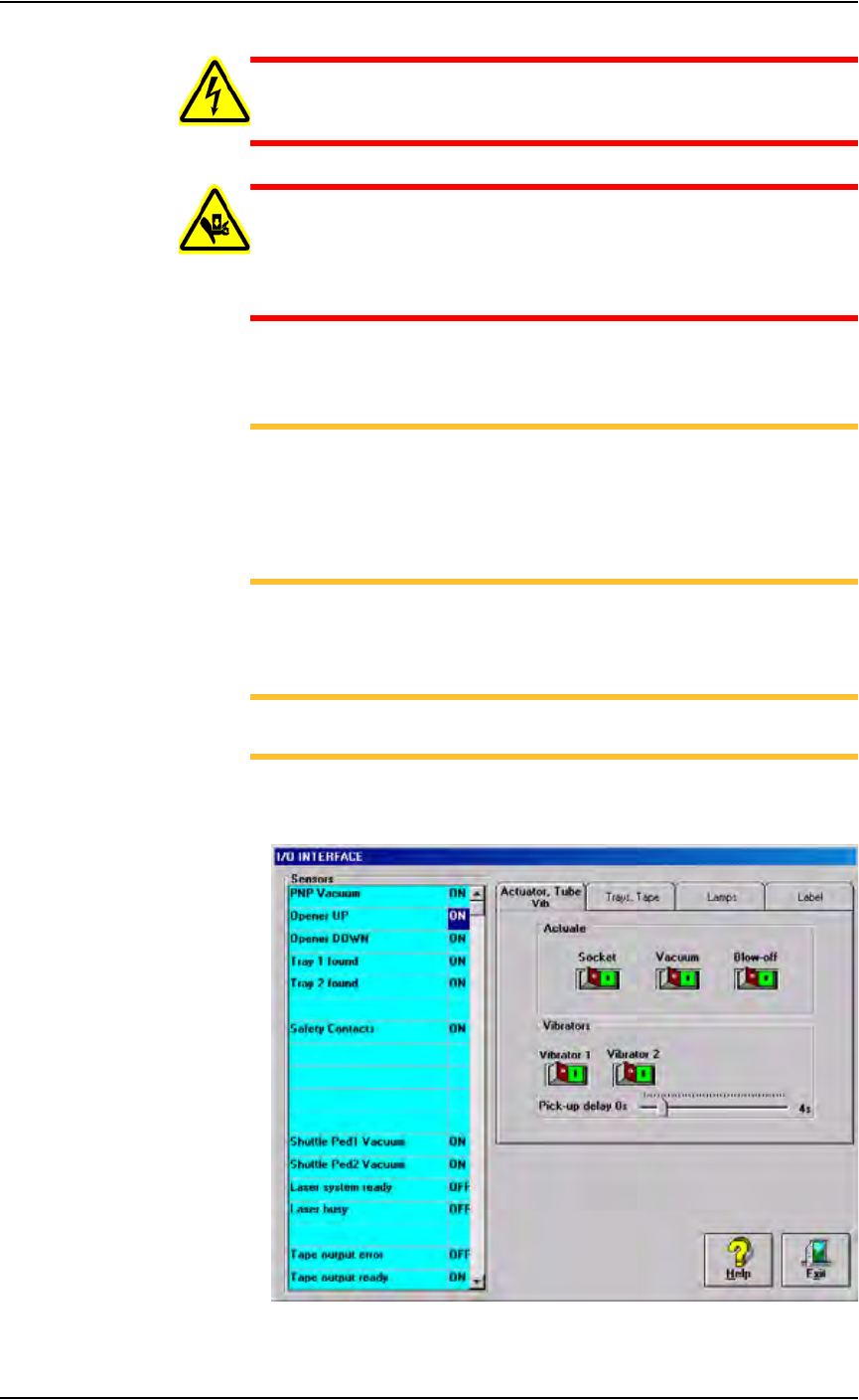
Vacuum sensors on the PS288 are adjustable. The I/O Interface window
displays a list of the sensors in the PS288 and the status of each sensor.
NOTE: The number of sensors on the PS288 depends on the
options installed.
To view the status of sensors in the system, on the AH500 main window
click System, and then click Misc. I/O to open the I/O Interface window.
Figure 5-29—I/O Interface window
Maintenance • Adjustments, Calibrations, and Functional Tests
PS288 Owner’s Manual 5—31
• The PS288 has an adjustable vacuum generator sensor on the PNP
head. See “PNP Head Vacuum Generator Sensor” on page 31
• If the PS288 has the optional label or laser marking system, or the
optional tape output system, there are adjustable vacuum generator sen-
sors for the shuttle transfer system. See “Shuttle Ped 1 and 2 Vacuum
Generator Sensors” on page 32
• If the PS288 has the optional tape output system, there is an adjustable
vacuum generator sensor on the tape output PNP head. See “Tape Out-
put PNP Head Vacuum Generator Sensor” on page 34.
PNP Head Vacuum Generator Sensor
1. Gantry window—
1a) On the Gantry window, move the PNP head to either the Tape or Vision
location.
NOTE: To move the PNP head, on the touch screen place the arrow
over either the Tape or Vision location and right-click the touchpad.
1b) Click the Gantry Vacuum switch to ON.
2. Vacuum sensor—
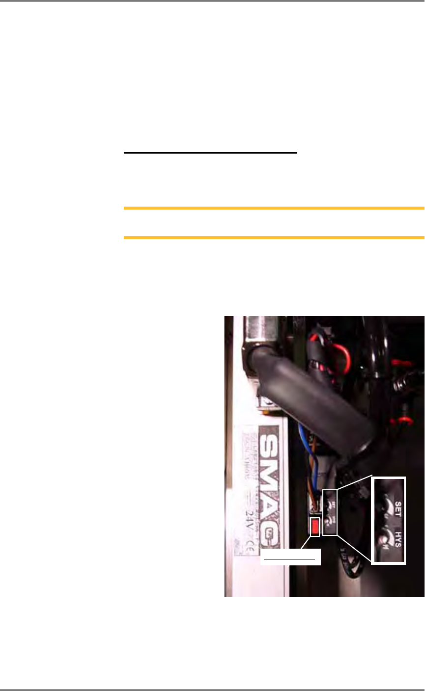
On the vacuum generator sensor, locate the adjustment screws labeled
HYS and SET. Locate the red sensor light. See Figure 5-30.
Figure 5-30—Vacuum sensor light. SET and HYS adjustment screws
Red sensor light
Maintenance • Adjustments, Calibrations, and Functional Tests
5—32 PS288 Owner’s Manual
3. Adjust the HYS and SET screws—
3a) Using a small flat screwdriver, turn the HYS screw all the way counter-
clockwise.
3b) Then turn the SET screw counterclockwise until the red sensor light
comes on.
3c) Then turn the SET screw clockwise until the red light goes off.
3d) Finally turn the SET screw another 1/8th turn clockwise.
4. Check adjustments—
4a) Block the hole on the PNP probe tip with a device. The red sensor light
should come on immediately.
4b) Unblock the hole. The red sensor light should go off immediately.
5. Repeat—
5a) Repeat Step 4 three times to ensure the red sensor light goes on and off
as described.
5b) If the red sensor light does not go off and on properly, turn the SET
screw slightly clockwise and retry.
Shuttle Ped 1 and 2 Vacuum Generator Sensors
1. Prepare the system—
1a) On the back of the PS288, turn the “SERVOS” circuit breaker OFF.
1b) Remove the right lower access cover of the Option Bay.
1c) Set the cover aside.
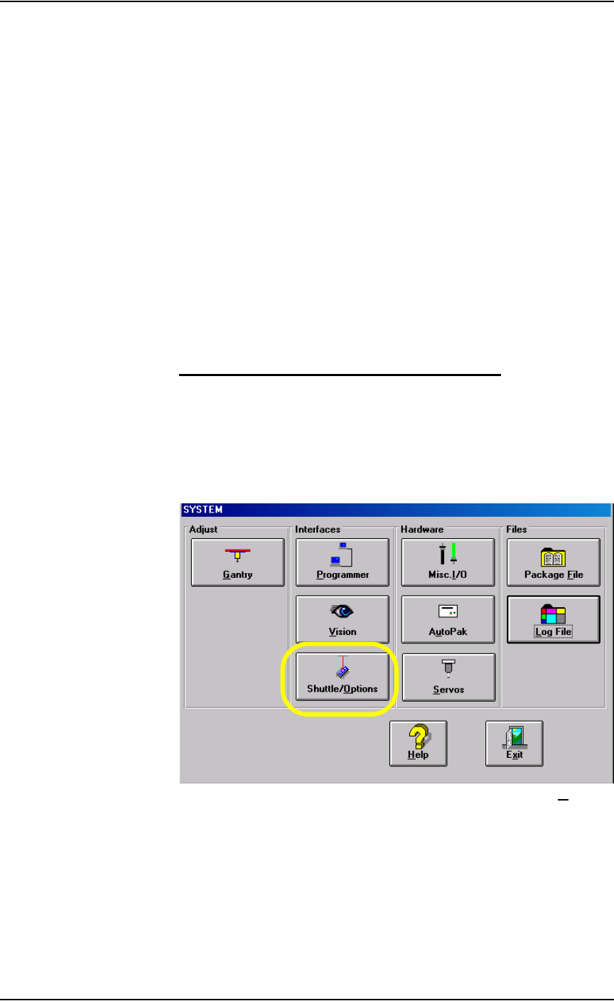
2. AH500 software—
2a) On the System window, click Shuttle/Options.
Figure 5-31—Click Shuttle/O
ptions
2b) On the Shuttle tab, click GO next to Ped 2 Load Pos. Then click the
Ped 2 Vacuum to ON. See Figure 5-32.