PS288_OwnersMnl_PriorTo2009 - 第169页
Maintenance • Adjustments, Calibrations, and Function al Tests 5—34 PS288 Owner’s Manual Figur e 5-33—Cup 1 and Cup 2 vacuum generator adjustments 6. Shuttle tab— 6a) Click Ped 1 V acuum to OFF . 6b) Click Ped 2 V acuum …
Maintenance • Adjustments, Calibrations, and Functional Tests
PS288 Owner’s Manual 5—33
.
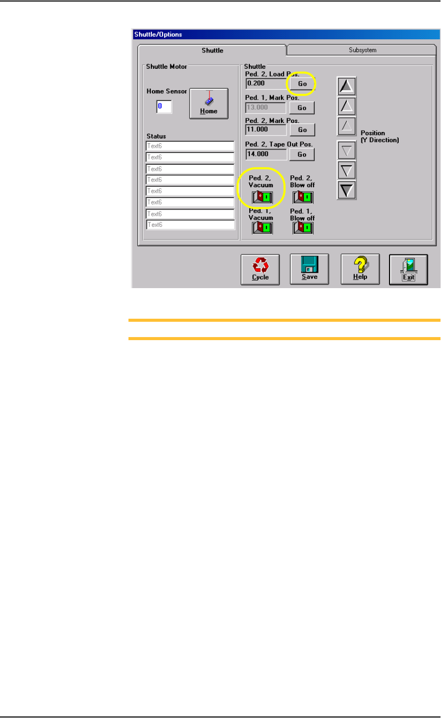
Figure 5-32—Click Go and then turn Ped 2 Vacuum ON
NOTE: Refer to Figure 5-33 for Step 3 through Step 5.
3. Adjust Cup 2 HYS and SET screws—
3a) Using a small flat screwdriver, turn the HYS screw all the way counter-
clockwise.
3b) Then turn the SET screw counterclockwise until the red vacuum sensor
light comes on.
3c) Then turn the SET screw clockwise until the light goes off.
3d) Finally turn the SET screw another 1/8th turn clockwise.
4. Check adjustment—
4a) Block the hole on the shuttle pedestal. The red vacuum sensor light
should come on immediately.
4b) Unblock the hole. The red vacuum sensor light should go off immedi-
ately.
4c) Repeat check to ensure the red vacuum sensor light goes on and off as
described.
4d) If the red vacuum sensor light does not go off and on properly, turn the
SET screw slightly clockwise and retry.
5. Adjust Cup 1 HYS and SET screw—
Repeat Step 3and Step 4 for Cup 1.
Maintenance • Adjustments, Calibrations, and Functional Tests
5—34 PS288 Owner’s Manual
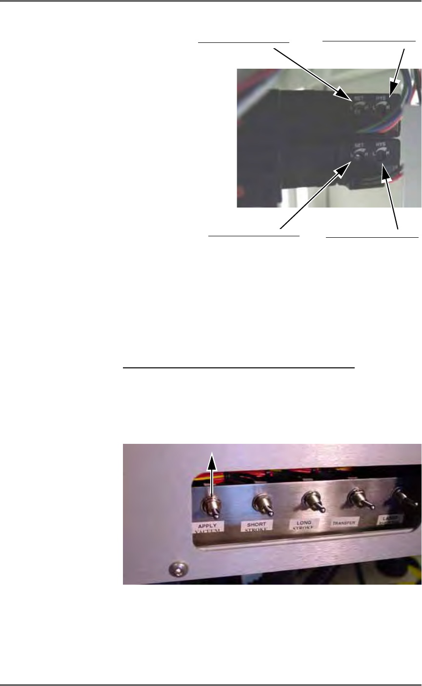
Figure 5-33—Cup 1 and Cup 2 vacuum generator adjustments
6. Shuttle tab—
6a) Click Ped 1 Vacuum to OFF.
6b) Click Ped 2 Vacuum to ON.
7. Reinstall cover—
Reinstall access cover on the Option Bay.
Tape Output PNP Head Vacuum Generator Sensor
If your system includes the optional tape output system, you will also need
to adjust the vacuum generator sensor on the tape output PNP head.
1. Prepare the system—
1a) On the PLC Controller, turn the Apply Vacuum switch to the ON (up)
position. See Figure 5-34.
Figure 5-34—Apply Vacuum switch UP
1b) Lift the clear plastic cover.
Cup 2 HYS adjustment screw
Cup 2 SET adjustment screw
Cup 1 HYS adjustment screw
Cup 1 HYS adjustment screw
Cup 1 SET adjustment screw

Maintenance • Adjustments, Calibrations, and Functional Tests
PS288 Owner’s Manual 5—35
2. Vacuum sensor—
On the vacuum sensor, locate the adjustment screws labeled HYS and
SET. See Figure 5-35.
Figure 5-35—HYS and Set screw locations
3. Adjust the HYS and SET screws—
3a) Using a small flat screwdriver, turn the HYS screw counterclockwise.
3b) Then turn the SET screw counterclockwise until the red vacuum sensor
light comes on.
3c) Then turn the SET screw clockwise until the light goes off.
3d) Finally turn the SET screw another 1/8th turn clockwise.
4. Check adjustments—
4a) Block the hole on the tape output PNP head. The red vacuum sensor
light should come on immediately.
4b) Unblock the hole. The red vacuum sensor light should go off immedi-
ately.
5. Repeat—
5a) Repeat Step 4 three times to ensure the red vacuum sensor light goes on
and off as described.
5b) If the red vacuum sensor light does not go off and on properly, turn the
SET screw slightly clockwise and retry.
6. Complete—
Close the clear plastic cover.
NOTE: If the hysteresis adjustment is set too high, the PS288 may
return a vacuum error due to its inability to sense a vacuum within
the time limits set in the AH500 software. The delay should be set as
short as possible to prevent this occurrence. However, if the delay is
set too short, vacuum line pulsations from usage throughout the rest
of the system could inadvertently turn the sensor on when it should
be off. Adjustments should be made to accommodate both condi-
tions.
HYS adjustment screw
SET adjustment screw