PS288_OwnersMnl_PriorTo2009 - 第171页
Maintenance • Adjustments, Calibrations, and Function al Tests 5—36 PS288 Owner’s Manual Adjusting the Blow-Off Pressure NOTE: The flow contr ols ar e set at the factory and should not r equir e adjustment. If adjust men…
Maintenance • Adjustments, Calibrations, and Functional Tests
PS288 Owner’s Manual 5—35
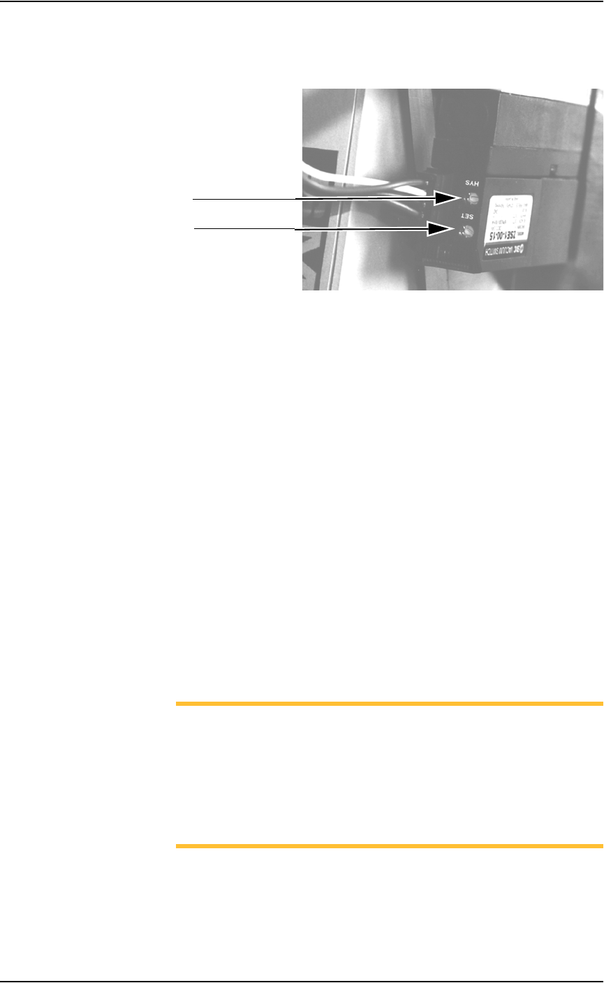
2. Vacuum sensor—
On the vacuum sensor, locate the adjustment screws labeled HYS and
SET. See Figure 5-35.
Figure 5-35—HYS and Set screw locations
3. Adjust the HYS and SET screws—
3a) Using a small flat screwdriver, turn the HYS screw counterclockwise.
3b) Then turn the SET screw counterclockwise until the red vacuum sensor
light comes on.
3c) Then turn the SET screw clockwise until the light goes off.
3d) Finally turn the SET screw another 1/8th turn clockwise.
4. Check adjustments—
4a) Block the hole on the tape output PNP head. The red vacuum sensor
light should come on immediately.
4b) Unblock the hole. The red vacuum sensor light should go off immedi-
ately.
5. Repeat—
5a) Repeat Step 4 three times to ensure the red vacuum sensor light goes on
and off as described.
5b) If the red vacuum sensor light does not go off and on properly, turn the
SET screw slightly clockwise and retry.
6. Complete—
Close the clear plastic cover.
NOTE: If the hysteresis adjustment is set too high, the PS288 may
return a vacuum error due to its inability to sense a vacuum within
the time limits set in the AH500 software. The delay should be set as
short as possible to prevent this occurrence. However, if the delay is
set too short, vacuum line pulsations from usage throughout the rest
of the system could inadvertently turn the sensor on when it should
be off. Adjustments should be made to accommodate both condi-
tions.
HYS adjustment screw
SET adjustment screw
Maintenance • Adjustments, Calibrations, and Functional Tests
5—36 PS288 Owner’s Manual
Adjusting the Blow-Off Pressure
NOTE: The flow controls are set at the factory and should not
require adjustment. If adjustments need to be made, they should be
done in small steps until the desired results are reached.
“Blow-off” is a small puff of positive pressure air applied for a short time
during the drop period to assist in removing a device from the suction cup.
Blow-off is produced by vacuum generators on the PNP head (or the tape
output PNP head, if installed). If set too high, blow-off may cause a mis-
alignment during device placement.
To adjust blow-off pressure on any vacuum generator:
1. Prepare the system—
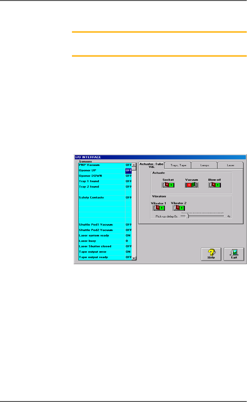
1a) From the I/O Interface window, select the desired vacuum generator.
1b) Click Vacuum to the OFF position.
1c) Click Blow off to the ON position.
Figure 5-36—I/O Interface
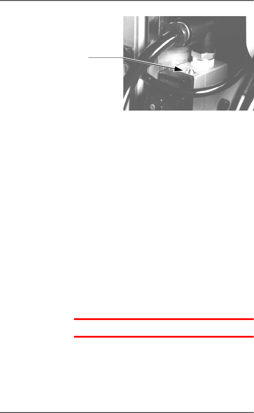
2. Vacuum generator—
On the top of the vacuum generator, locate the blow-off adjustment
screw above the valve coils (where the wires plug in). See Figure 5-37.
Maintenance • Adjustments, Calibrations, and Functional Tests
PS288 Owner’s Manual 5—37
Figure 5-37—Blow-off adjustment screw on vacuum generator
3. Adjust—
3a) Turn the adjustment screw fully clockwise. This blocks all air and there
is no “blow-off” puff of air at the probe tip.
3b) Turn the adjustment screw about 1/2 turn counterclockwise.
Adjusting the Socket Actuator Air Pressure
If the PNP head does not properly place or pick a device in a socket because
the socket is not opening completely, the Socket Actuator air pressure may
be set too low.
To adjust the Socket Actuator air pressure:
1. Prepare the system—
1a) Pause any Job that is running.
1b) On the Gantry window, select the Actuator tab.
1c) Verify the Socket switch is ON.
2. Input panel—
2a) Verify that the Socket Actuator pressure regulator is set in the 138-276
kiloPascals (20–40 PSI) range.
2b) Increase the Socket Actuator air pressure slightly (within the range).
3. Restart Job—
3a) Restart the job and check the action of the Socket Actuator.
3b) Increase Socket Actuator air pressure if needed.
CAUTION: Setting the Socket Actuator air pressure too high can
cause premature wear of the sockets.
Adjusting the Socket Actuator Sensors
The Socket Actuator sensor tells the AH500 software the position of the
Socket Actuator (up or down), and when a device can be put into a socket.
To adjust the Socket Actuator sensor:
Adjustment screw