PS288_OwnersMnl_PriorTo2009 - 第172页
Maintenance • Adjustments, Calibrations, and Function al Tests PS288 Owner’s Manual 5—37 Figur e 5-37—Blow-off adjustment scr ew on vacuum gen erator 3. Adjust— 3a) T urn the adjustment screw fully cloc kwise. This block…
Maintenance • Adjustments, Calibrations, and Functional Tests
5—36 PS288 Owner’s Manual
Adjusting the Blow-Off Pressure
NOTE: The flow controls are set at the factory and should not
require adjustment. If adjustments need to be made, they should be
done in small steps until the desired results are reached.
“Blow-off” is a small puff of positive pressure air applied for a short time
during the drop period to assist in removing a device from the suction cup.
Blow-off is produced by vacuum generators on the PNP head (or the tape
output PNP head, if installed). If set too high, blow-off may cause a mis-
alignment during device placement.
To adjust blow-off pressure on any vacuum generator:
1. Prepare the system—
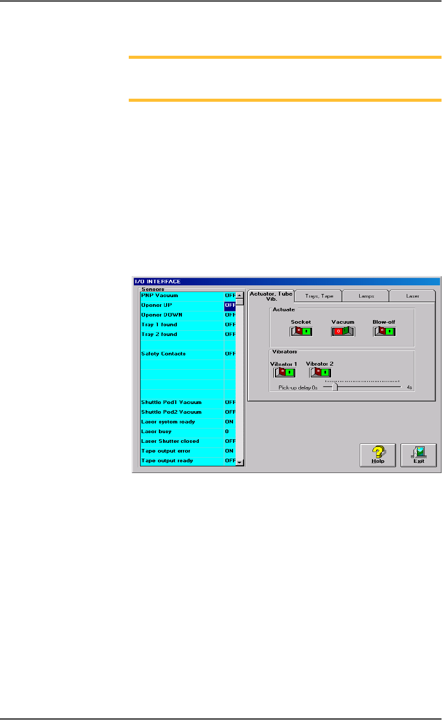
1a) From the I/O Interface window, select the desired vacuum generator.
1b) Click Vacuum to the OFF position.
1c) Click Blow off to the ON position.
Figure 5-36—I/O Interface
2. Vacuum generator—
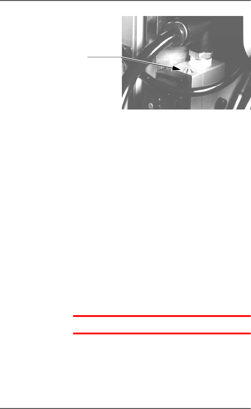
On the top of the vacuum generator, locate the blow-off adjustment
screw above the valve coils (where the wires plug in). See Figure 5-37.
Maintenance • Adjustments, Calibrations, and Functional Tests
PS288 Owner’s Manual 5—37
Figure 5-37—Blow-off adjustment screw on vacuum generator
3. Adjust—
3a) Turn the adjustment screw fully clockwise. This blocks all air and there
is no “blow-off” puff of air at the probe tip.
3b) Turn the adjustment screw about 1/2 turn counterclockwise.
Adjusting the Socket Actuator Air Pressure
If the PNP head does not properly place or pick a device in a socket because
the socket is not opening completely, the Socket Actuator air pressure may
be set too low.
To adjust the Socket Actuator air pressure:
1. Prepare the system—
1a) Pause any Job that is running.
1b) On the Gantry window, select the Actuator tab.
1c) Verify the Socket switch is ON.
2. Input panel—
2a) Verify that the Socket Actuator pressure regulator is set in the 138-276
kiloPascals (20–40 PSI) range.
2b) Increase the Socket Actuator air pressure slightly (within the range).
3. Restart Job—
3a) Restart the job and check the action of the Socket Actuator.
3b) Increase Socket Actuator air pressure if needed.
CAUTION: Setting the Socket Actuator air pressure too high can
cause premature wear of the sockets.
Adjusting the Socket Actuator Sensors
The Socket Actuator sensor tells the AH500 software the position of the
Socket Actuator (up or down), and when a device can be put into a socket.
To adjust the Socket Actuator sensor:
Adjustment screw
Maintenance • Adjustments, Calibrations, and Functional Tests
5—38 PS288 Owner’s Manual
1. Prepare the system—
1a) From the Setup window, click System.
1b) On the System window, click Gantry to open the Gantry window.
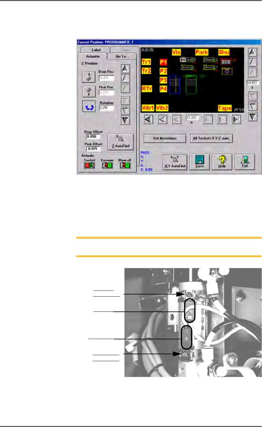
Figure 5-38—Gantry window
1c) Click on any programmer label (P1 through P4) to move the PNP head
to that programmer.
1d) On the PNP head, locate the up sensor and up sensor bracket screw.
Locate the down sensor and down sensor bracket screw. See Figure
5-39.
NOTE: On some PS288s, the up sensor and down sensor contain
LEDs that indicate the position of the Socket Actuator.
Figure 5-39—Sensors and brackets as viewed from back of PNP head
2. Adjust up sensor—
2a) Loosen the Phillips-head screw on the up sensor bracket.
Down sensor
bracket screw
Up sensor
bracket screw
Down sensor
Up sensor