PS288_OwnersMnl_PriorTo2009 - 第173页
Maintenance • Adjustments, Calibrations, and Function al Tests 5—38 PS288 Owner’s Manual 1. Prepar e the system— 1a) From the Setup window , cli ck System . 1b) On the System window , click Gantry to open the Gantry wind…
Maintenance • Adjustments, Calibrations, and Functional Tests
PS288 Owner’s Manual 5—37
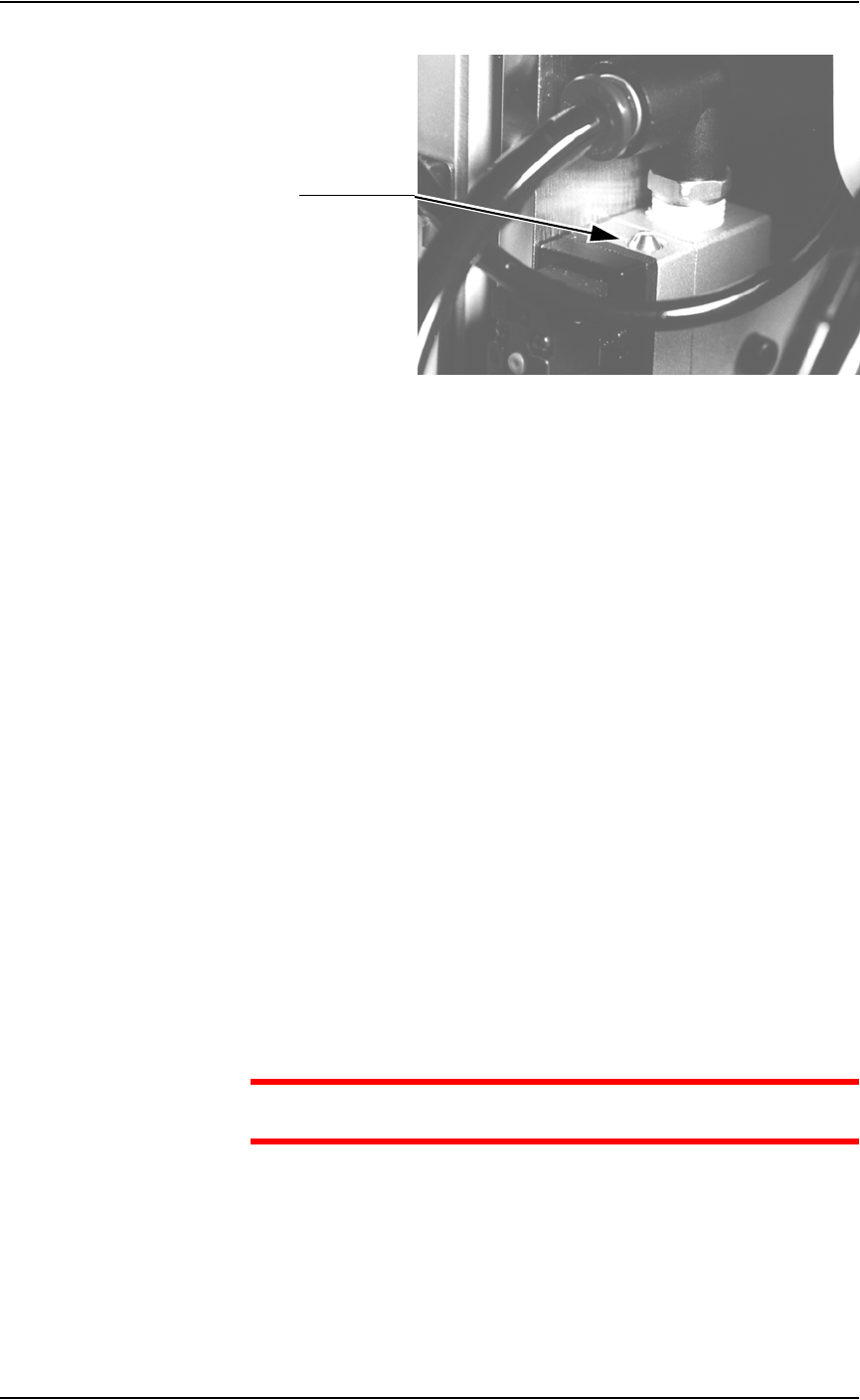
Figure 5-37—Blow-off adjustment screw on vacuum generator
3. Adjust—
3a) Turn the adjustment screw fully clockwise. This blocks all air and there
is no “blow-off” puff of air at the probe tip.
3b) Turn the adjustment screw about 1/2 turn counterclockwise.
Adjusting the Socket Actuator Air Pressure
If the PNP head does not properly place or pick a device in a socket because
the socket is not opening completely, the Socket Actuator air pressure may
be set too low.
To adjust the Socket Actuator air pressure:
1. Prepare the system—
1a) Pause any Job that is running.
1b) On the Gantry window, select the Actuator tab.
1c) Verify the Socket switch is ON.
2. Input panel—
2a) Verify that the Socket Actuator pressure regulator is set in the 138-276
kiloPascals (20–40 PSI) range.
2b) Increase the Socket Actuator air pressure slightly (within the range).
3. Restart Job—
3a) Restart the job and check the action of the Socket Actuator.
3b) Increase Socket Actuator air pressure if needed.
CAUTION: Setting the Socket Actuator air pressure too high can
cause premature wear of the sockets.
Adjusting the Socket Actuator Sensors
The Socket Actuator sensor tells the AH500 software the position of the
Socket Actuator (up or down), and when a device can be put into a socket.
To adjust the Socket Actuator sensor:
Adjustment screw
Maintenance • Adjustments, Calibrations, and Functional Tests
5—38 PS288 Owner’s Manual
1. Prepare the system—
1a) From the Setup window, click System.
1b) On the System window, click Gantry to open the Gantry window.
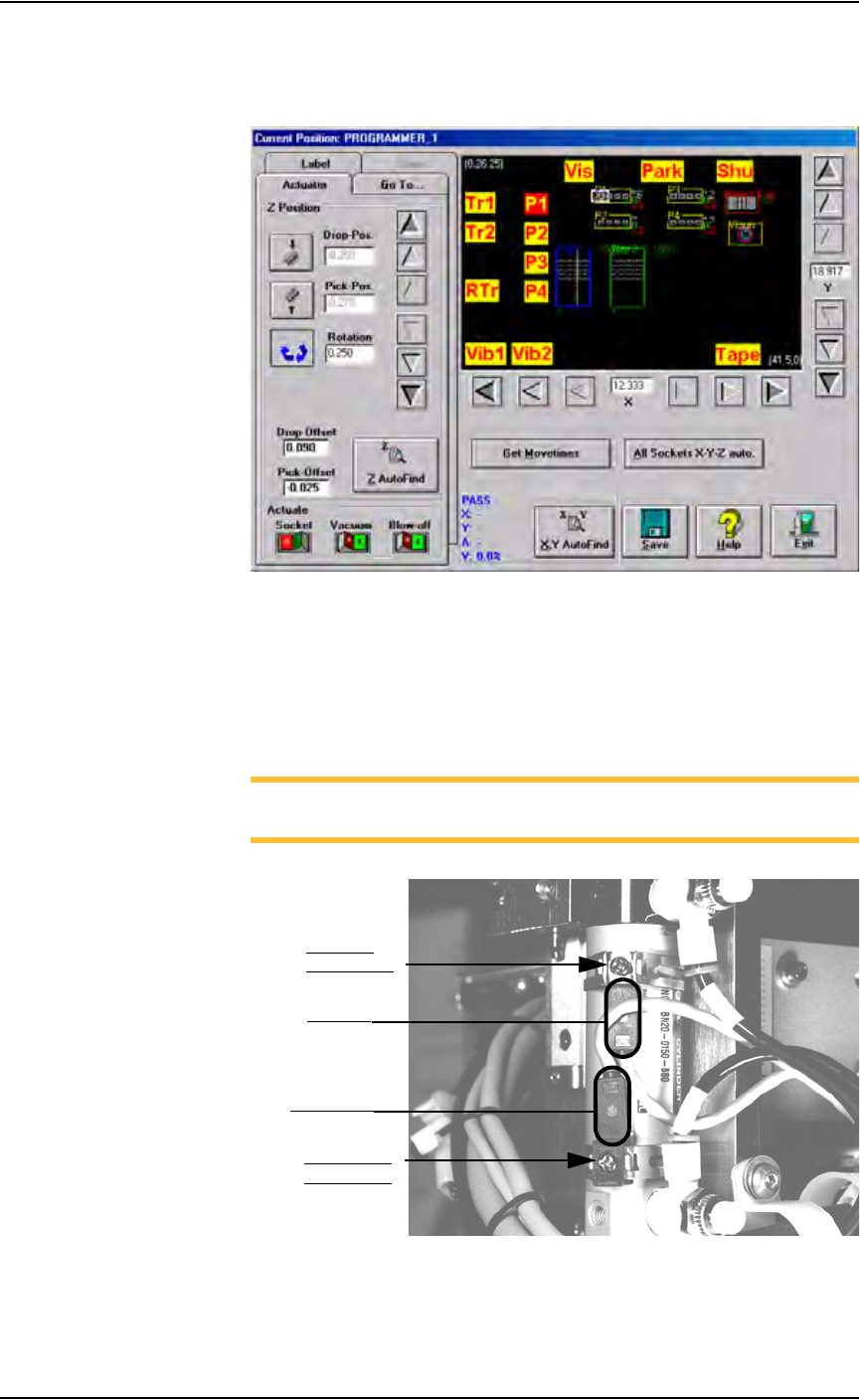
Figure 5-38—Gantry window
1c) Click on any programmer label (P1 through P4) to move the PNP head
to that programmer.
1d) On the PNP head, locate the up sensor and up sensor bracket screw.
Locate the down sensor and down sensor bracket screw. See Figure
5-39.
NOTE: On some PS288s, the up sensor and down sensor contain
LEDs that indicate the position of the Socket Actuator.
Figure 5-39—Sensors and brackets as viewed from back of PNP head
2. Adjust up sensor—
2a) Loosen the Phillips-head screw on the up sensor bracket.
Down sensor
bracket screw
Up sensor
bracket screw
Down sensor
Up sensor
Maintenance • Adjustments, Calibrations, and Functional Tests
PS288 Owner’s Manual 5—39
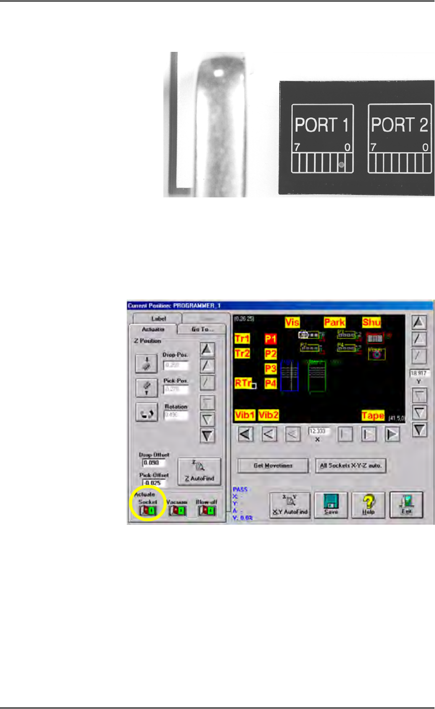
2b) Move the up sensor upwards until the green I/O Controller LED for
Port 1, Bit 1 illuminates. See Figure 5-40.
Figure 5-40—Port 1, Bit 1 LED illuminated
2c) Tighten the up sensor bracket screw.
2d) On the Actuator tab, click Socket to the ON position.
3. Adjust down sensor—
3a) On the Gantry window, ensure the Socket Actuator to toggled to the
ON position. (see Figure 5-41). The Socket Actuator moves down.
Figure 5-41—Socket actuator ON
3b) On the input panel (on the rear of PS288), push the yellow bar down to
shut off the input air (see Figure 5-42).