PS288_OwnersMnl_PriorTo2009 - 第174页
Maintenance • Adjustments, Calibrations, and Function al Tests PS288 Owner’s Manual 5—39 2b) Move the up sensor upwards until the green I/O Cont roller LED for Port 1, Bit 1 illu minates. See Figur e 5-40 . Figur e 5-40—…
Maintenance • Adjustments, Calibrations, and Functional Tests
5—38 PS288 Owner’s Manual
1. Prepare the system—
1a) From the Setup window, click System.
1b) On the System window, click Gantry to open the Gantry window.
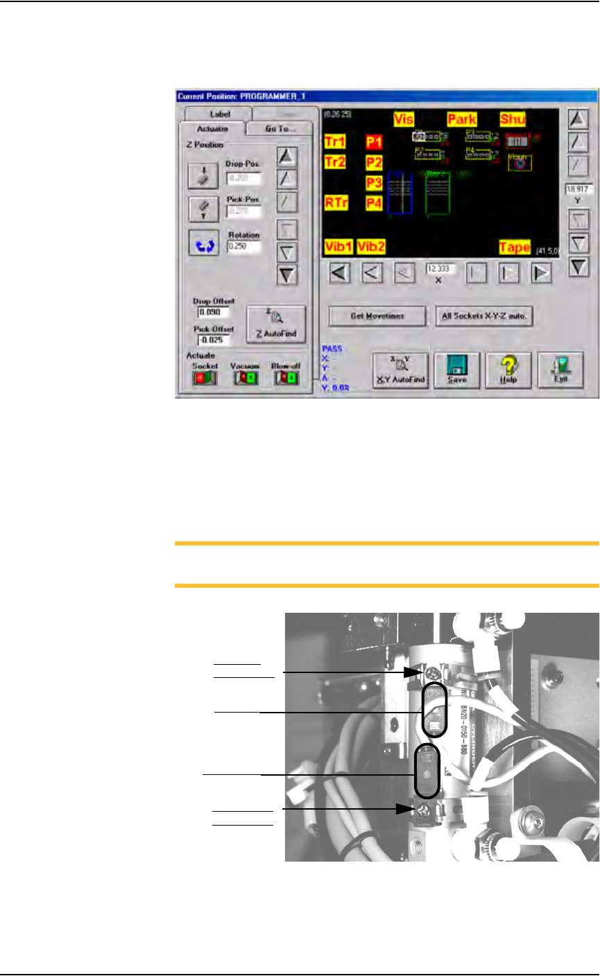
Figure 5-38—Gantry window
1c) Click on any programmer label (P1 through P4) to move the PNP head
to that programmer.
1d) On the PNP head, locate the up sensor and up sensor bracket screw.
Locate the down sensor and down sensor bracket screw. See Figure
5-39.
NOTE: On some PS288s, the up sensor and down sensor contain
LEDs that indicate the position of the Socket Actuator.
Figure 5-39—Sensors and brackets as viewed from back of PNP head
2. Adjust up sensor—
2a) Loosen the Phillips-head screw on the up sensor bracket.
Down sensor
bracket screw
Up sensor
bracket screw
Down sensor
Up sensor
Maintenance • Adjustments, Calibrations, and Functional Tests
PS288 Owner’s Manual 5—39
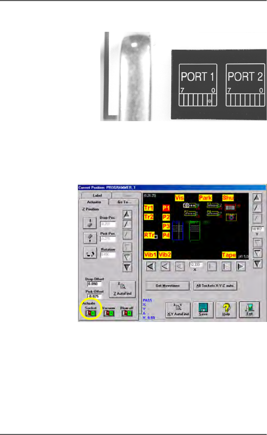
2b) Move the up sensor upwards until the green I/O Controller LED for
Port 1, Bit 1 illuminates. See Figure 5-40.
Figure 5-40—Port 1, Bit 1 LED illuminated
2c) Tighten the up sensor bracket screw.
2d) On the Actuator tab, click Socket to the ON position.
3. Adjust down sensor—
3a) On the Gantry window, ensure the Socket Actuator to toggled to the
ON position. (see Figure 5-41). The Socket Actuator moves down.
Figure 5-41—Socket actuator ON
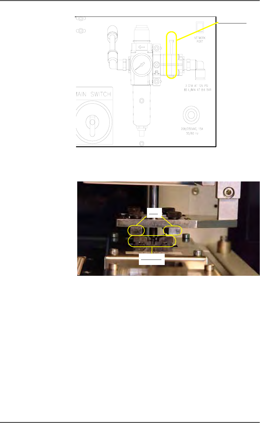
3b) On the input panel (on the rear of PS288), push the yellow bar down to
shut off the input air (see Figure 5-42).
Maintenance • Adjustments, Calibrations, and Functional Tests
5—40 PS288 Owner’s Manual
Figure 5-42—Push bar down on main air valve to turn off air
3c) By hand, move the Socket Actuator down until the Socket Actuator
ribs make contact with the socket top. See Figure 5-43.
Figure 5-43—Socket actuator ribs contact socket top
3d) Loosen the Phillips-head screw on the down sensor bracket.
3e) Move the down sensor downward until the red LED on the sensor turns
on. At this time, the green I/O Controller LED for Port 1, Bit 2 also
illuminates.
3f) Tighten the down sensor bracket screw.
3g) By hand, push the Socket Actuator down farther and ensure that
I/O Controller LED Port 1, Bit 2 remains illuminated.
3h) On the input panel (on rear of PS288), turn the Socket Actuator air
pressure to ON.
3i) Click the socket switch OFF and ON several times to verify that the
LED turns off and then on.
Main air valve
Ribs
Socket top