PS288_OwnersMnl_PriorTo2009 - 第175页
Maintenance • Adjustments, Calibrations, and Function al Tests 5—40 PS288 Owner’s Manual Figur e 5-42—Push bar down on main air valve to turn off air 3c) By hand, move the Socket Actuator down unti l the Socket Actuator …
Maintenance • Adjustments, Calibrations, and Functional Tests
PS288 Owner’s Manual 5—39
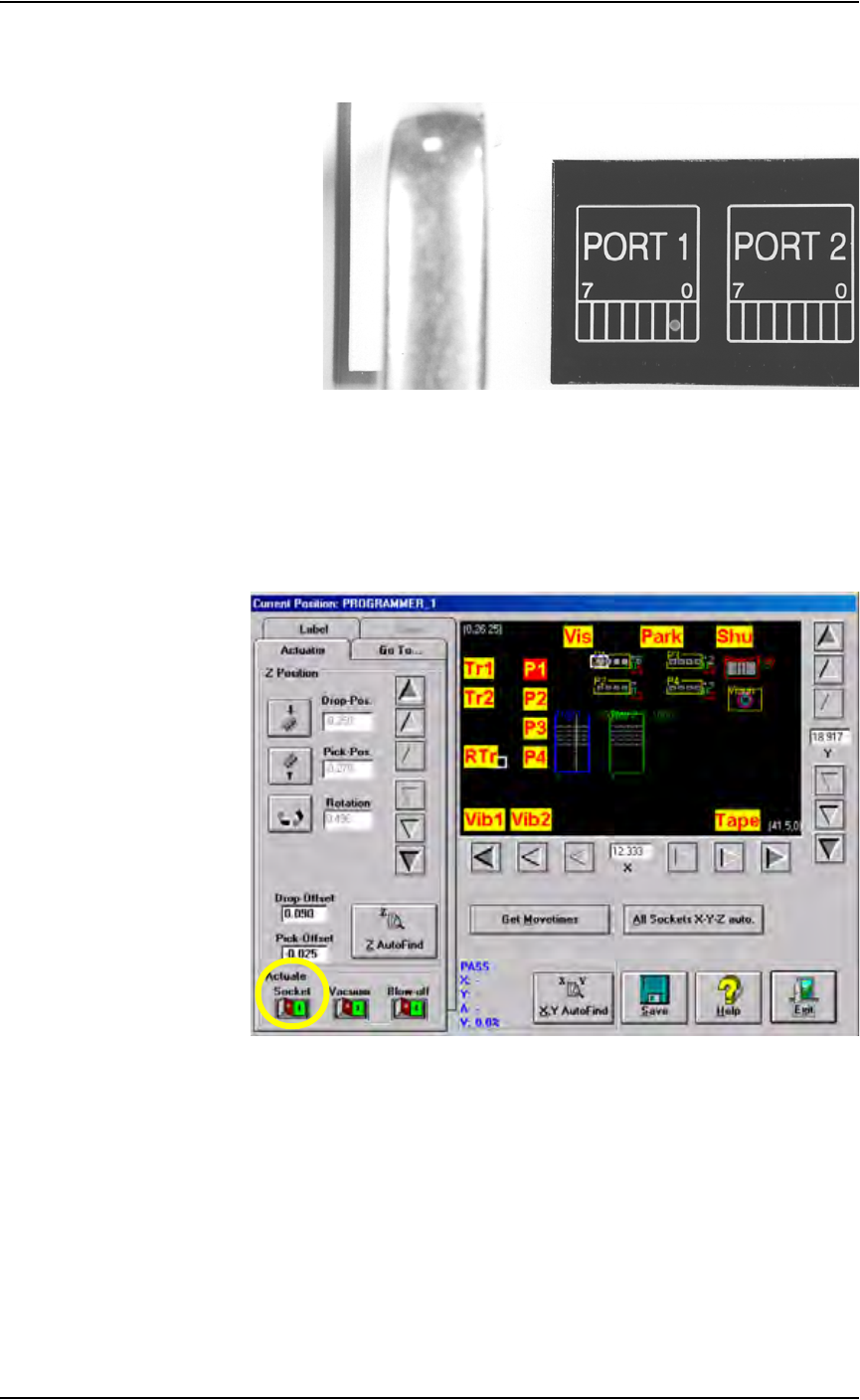
2b) Move the up sensor upwards until the green I/O Controller LED for
Port 1, Bit 1 illuminates. See Figure 5-40.
Figure 5-40—Port 1, Bit 1 LED illuminated
2c) Tighten the up sensor bracket screw.
2d) On the Actuator tab, click Socket to the ON position.
3. Adjust down sensor—
3a) On the Gantry window, ensure the Socket Actuator to toggled to the
ON position. (see Figure 5-41). The Socket Actuator moves down.
Figure 5-41—Socket actuator ON
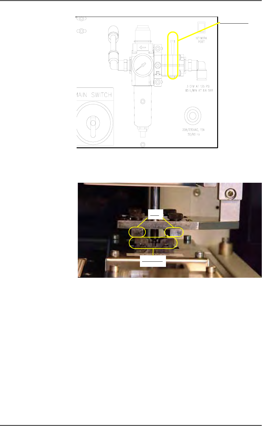
3b) On the input panel (on the rear of PS288), push the yellow bar down to
shut off the input air (see Figure 5-42).
Maintenance • Adjustments, Calibrations, and Functional Tests
5—40 PS288 Owner’s Manual
Figure 5-42—Push bar down on main air valve to turn off air
3c) By hand, move the Socket Actuator down until the Socket Actuator
ribs make contact with the socket top. See Figure 5-43.
Figure 5-43—Socket actuator ribs contact socket top
3d) Loosen the Phillips-head screw on the down sensor bracket.
3e) Move the down sensor downward until the red LED on the sensor turns
on. At this time, the green I/O Controller LED for Port 1, Bit 2 also
illuminates.
3f) Tighten the down sensor bracket screw.
3g) By hand, push the Socket Actuator down farther and ensure that
I/O Controller LED Port 1, Bit 2 remains illuminated.
3h) On the input panel (on rear of PS288), turn the Socket Actuator air
pressure to ON.
3i) Click the socket switch OFF and ON several times to verify that the
LED turns off and then on.
Main air valve
Ribs
Socket top

Maintenance • Adjustments, Calibrations, and Functional Tests
PS288 Owner’s Manual 5—41
Calibrating FlashCORE Programmers
PS288 power is provided by a switching power supply. Secondary voltages
are subsequently generated within the FlashCORE programmers to provide
the signals required for processing the many devices supported. To optimize
programming yields, voltages within the FlashCORE programmer must be
calibrated once each year.
For instructions, see “Testing and Calibrating FlashCORE Programmers” on
page 5-27
Calibrating the Vision System
The vision system provides for angular correction up to 30 degrees for
devices on the probe tip before they are placed in the programming socket.
This angular correction is performed to reduce the likelihood of device dam-
age from improper insertion.
If any of the following are true, the vision system may require calibration:
) The camera has been replaced, moved, refocused, or contrast changed
(by aperture setting or device position).
) Many devices are being misaligned or rejected, and you suspect the
motion settings or vision system may be at fault.
) There are continuity failures.
You will need:
Data I/O part number 695-0020-001 Vision Calibration Plate
1. Prepare the system—
1a) Start TaskLink and load a Job.
1b) In the AH500 Setup window, click System. If asked for a password,
provide the password and click System again.
1c) Click Gantry to open the Gantry window.
1d) Click Park and then Vis. Verify that the following values display at
both positions:
DropPos = -0.250
PickPos = -0.250
Rotation= 0.000