PS288_OwnersMnl_PriorTo2009 - 第177页
Maintenance • Adjustments, Calibrations, and Function al Tests 5—42 PS288 Owner’s Manual f Figur e 5-44—V erify values 1e) Open the package file fo r this job (for example: S273.txt ) and ensure the following value: Reco…

Maintenance • Adjustments, Calibrations, and Functional Tests
PS288 Owner’s Manual 5—41
Calibrating FlashCORE Programmers
PS288 power is provided by a switching power supply. Secondary voltages
are subsequently generated within the FlashCORE programmers to provide
the signals required for processing the many devices supported. To optimize
programming yields, voltages within the FlashCORE programmer must be
calibrated once each year.
For instructions, see “Testing and Calibrating FlashCORE Programmers” on
page 5-27
Calibrating the Vision System
The vision system provides for angular correction up to 30 degrees for
devices on the probe tip before they are placed in the programming socket.
This angular correction is performed to reduce the likelihood of device dam-
age from improper insertion.
If any of the following are true, the vision system may require calibration:
) The camera has been replaced, moved, refocused, or contrast changed
(by aperture setting or device position).
) Many devices are being misaligned or rejected, and you suspect the
motion settings or vision system may be at fault.
) There are continuity failures.
You will need:
Data I/O part number 695-0020-001 Vision Calibration Plate
1. Prepare the system—
1a) Start TaskLink and load a Job.
1b) In the AH500 Setup window, click System. If asked for a password,
provide the password and click System again.
1c) Click Gantry to open the Gantry window.
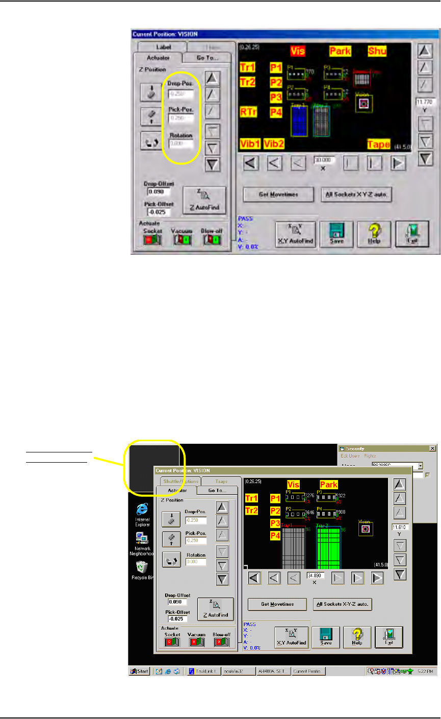
1d) Click Park and then Vis. Verify that the following values display at
both positions:
DropPos = -0.250
PickPos = -0.250
Rotation= 0.000
Maintenance • Adjustments, Calibrations, and Functional Tests
5—42 PS288 Owner’s Manual
f
Figure 5-44—Verify values
1e) Open the package file for this job (for example: S273.txt) and
ensure the following value:
Record #22 = 0
1f) Remove the clear plastic vision cover disk on the camera hole at the
Vision position.
1g) Mark the center of the cover disk with a washable felt pen or dry erase
marker.
1h) Replace the cover disk over the camera hole.
2. Set up AcuWin32—
2a) Within the Gantry window, click Vis to bring the PNP head to Vision.
2b) Double-click inside the small acuWin32 window in the upper left cor-
ner of the desktop.
.
Figure 5-45—Double-click inside acuWin32 window
Double-click inside
acuWin32 window
Maintenance • Adjustments, Calibrations, and Functional Tests
PS288 Owner’s Manual 5—43
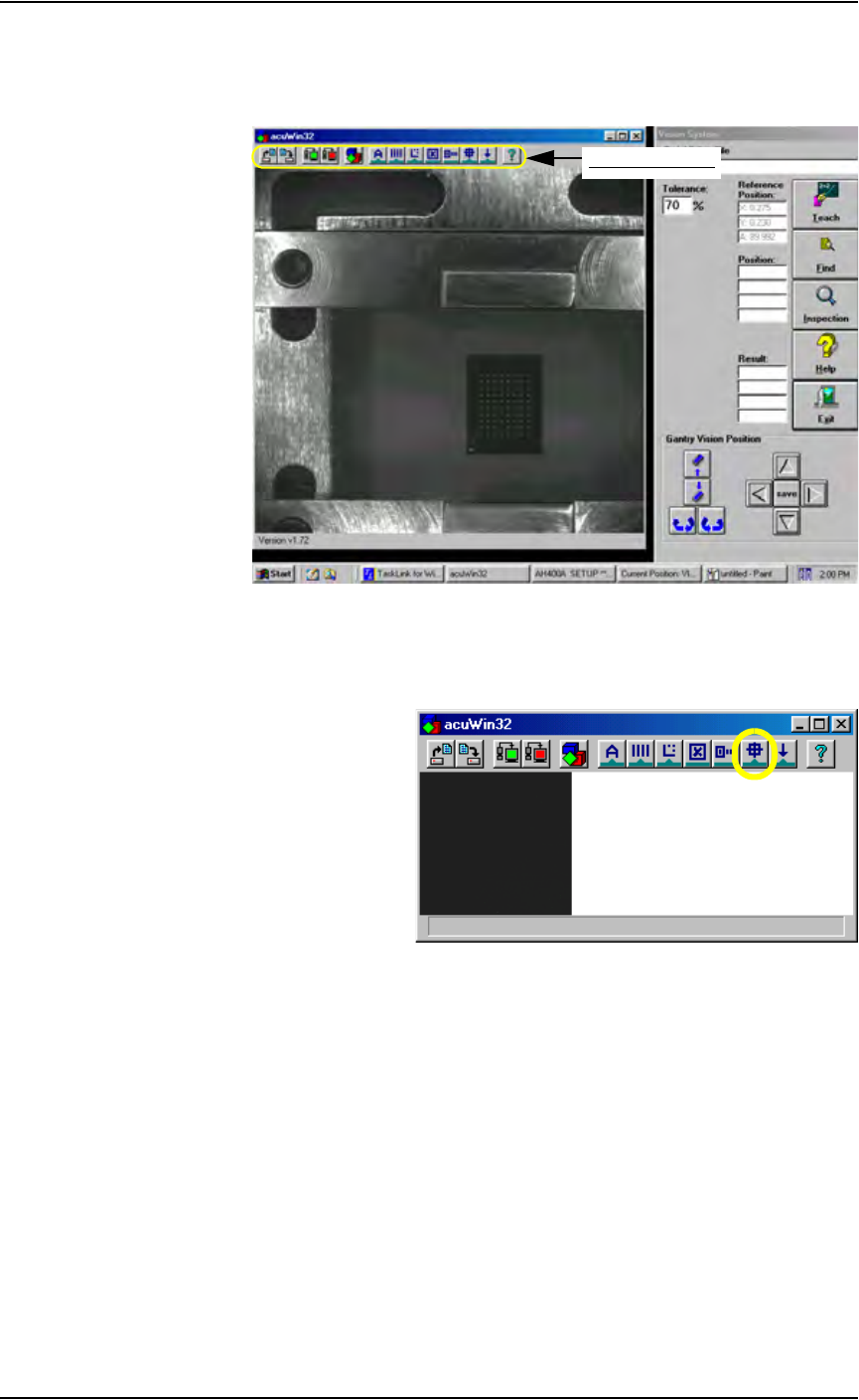
2c) Bring the cursor anywhere inside the black and white vision image area
shown below and double-click. This opens the acuWin32 tool bar. Fig-
ure 5-46 shows the tool bar open
Figure 5-46—Click inside black and white vision image area to open the
AcuWin32 tool bar
2d) On the acuWin32 tool bar, click the icon to open the Search Search dia-
log.
Figure 5-47— Click to switch to Search Search dialog
acuWin32 tool bar