PS288_OwnersMnl_PriorTo2009 - 第179页
Maintenance • Adjustments, Calibrations, and Function al Tests 5—44 PS288 Owner’s Manual 2e) On the Search Search dialog, click the icon to open the Display Obj- Man. Displa y dialog. Figur e 5-48—Click to open Display O…
Maintenance • Adjustments, Calibrations, and Functional Tests
PS288 Owner’s Manual 5—43
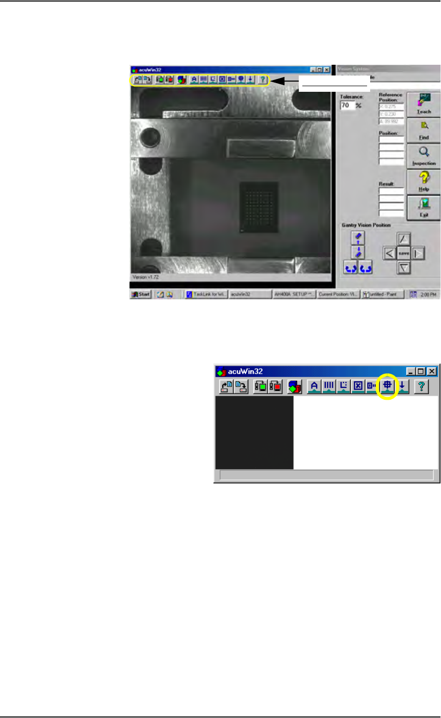
2c) Bring the cursor anywhere inside the black and white vision image area
shown below and double-click. This opens the acuWin32 tool bar. Fig-
ure 5-46 shows the tool bar open
Figure 5-46—Click inside black and white vision image area to open the
AcuWin32 tool bar
2d) On the acuWin32 tool bar, click the icon to open the Search Search dia-
log.
Figure 5-47— Click to switch to Search Search dialog
acuWin32 tool bar
Maintenance • Adjustments, Calibrations, and Functional Tests
5—44 PS288 Owner’s Manual
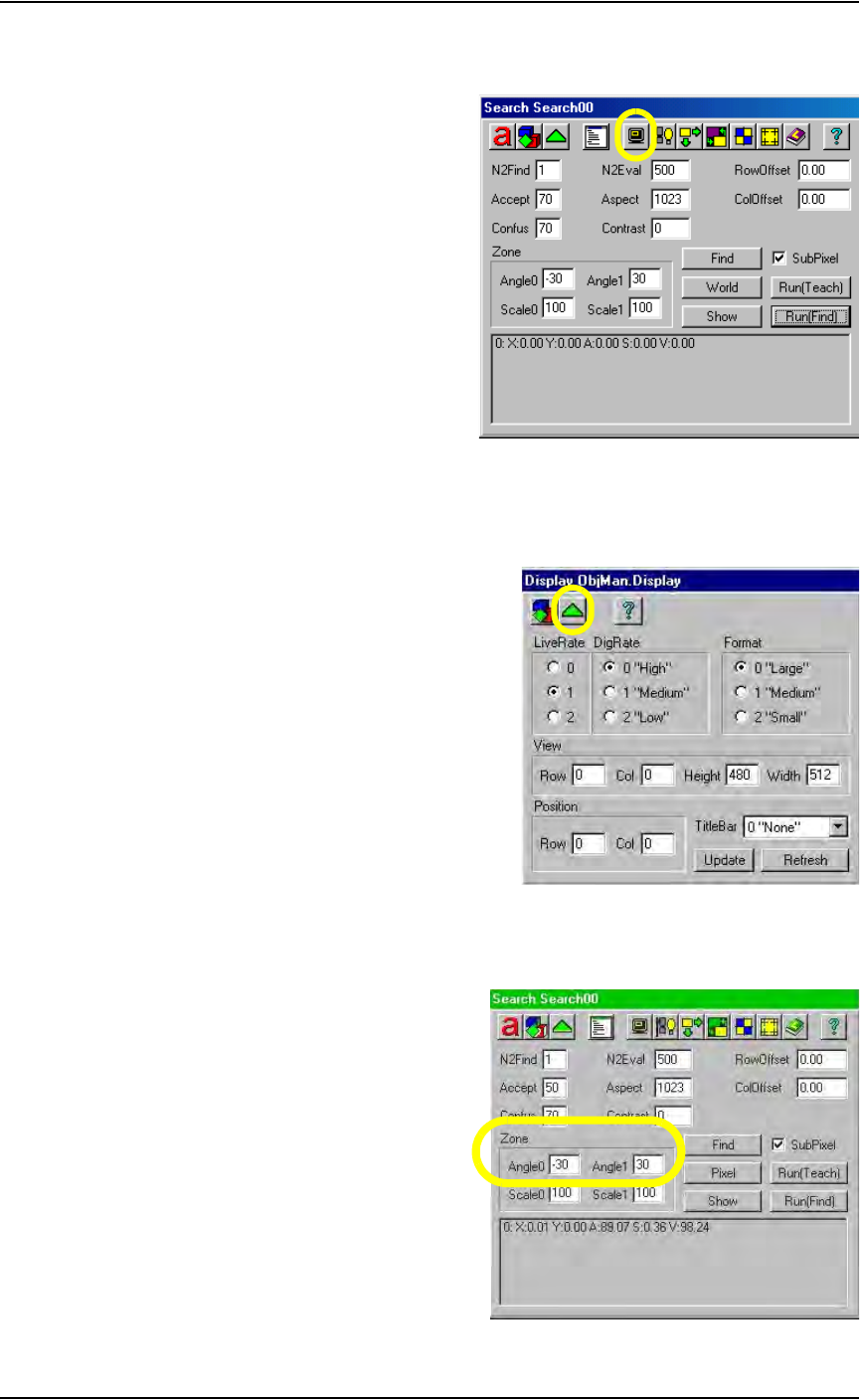
2e) On the Search Search dialog, click the icon to open the Display Obj-
Man. Display dialog.
Figure 5-48—Click to open Display ObjMan. Display dialog
2f) On the Display ObjMan.Display dialog, set the DigRate to 0 “High”
and the Format to 0 “Large.” Then press the green triangle to return to
the Search Search dialog. See Figure 5-49.
Figure 5-49—Display ObjMan.Display dialog settings
2g) On the Search Search dialog, set values in the Zone fields so that
Angle0 is -30 and Angle1 is 30. See Figure 5-50.
Figure 5-50—Set values in Zone fields
Maintenance • Adjustments, Calibrations, and Functional Tests
PS288 Owner’s Manual 5—45
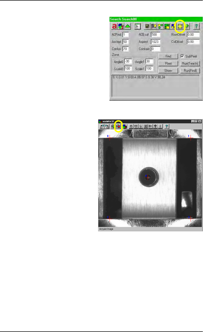
2h) Click the "Switch to Calib Object" dialog icon.
Figure 5-51—Click the "Switch to Calib Object" icon
2i) On the acuWin32 tool bar, click the icon to Acquire Image.
Figure 5-52—Acquire Image icon
3. Align cross hairs—
3a) The black dot marked on the vision cover will be visible as a dot or
white “blemish.”
3b) Return to the Gantry window. Using the adjustment buttons for the
X-axis and Y-axis, position the “blemish” so that it is in the center of
the vacuum pickup cup. Press the Red icon to Acquire Image after
adjusting the X-axis and the Y-axis. Repeat until the blemish is cen-
tered.
3c) Using the adjustment buttons for the X-axis and Y-axis, center
cross hair 4 on the vacuum pickup cup as well. When correctly
adjusted, the vacuum cup, “blemish” and Red Cross hair 4 are all lined
up, as shown in Figure 5-52.