PS288_OwnersMnl_PriorTo2009 - 第181页
Maintenance • Adjustments, Calibrations, and Function al Tests 5—46 PS288 Owner’s Manual 3d) In the Gantry window , turn the V acuum rock er switch to ON , as show n in Figur e 5-53 . Figur e 5-53—V acuu m switch is ON 3…
Maintenance • Adjustments, Calibrations, and Functional Tests
PS288 Owner’s Manual 5—45
2h) Click the "Switch to Calib Object" dialog icon.
Figure 5-51—Click the "Switch to Calib Object" icon
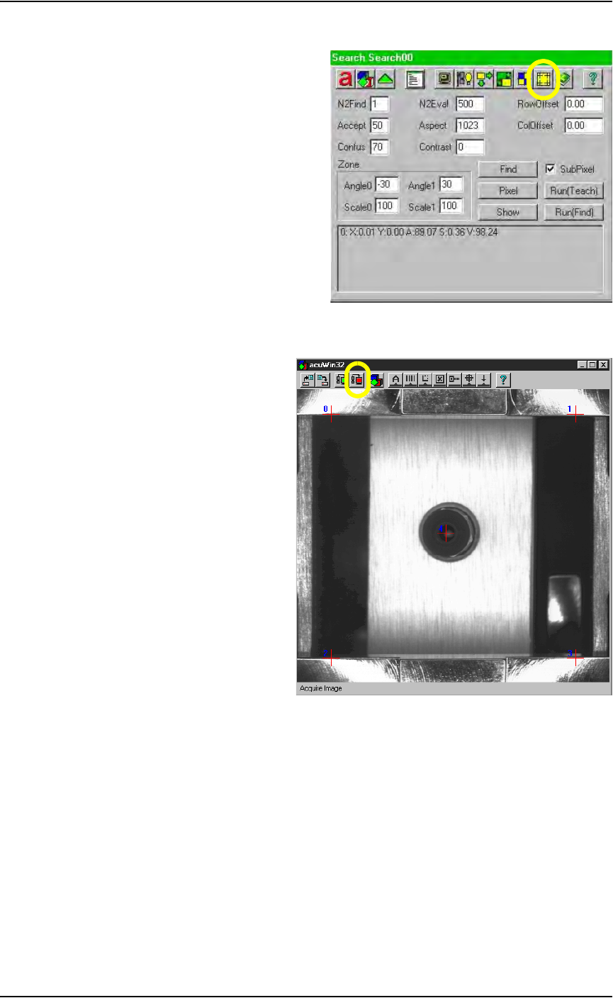
2i) On the acuWin32 tool bar, click the icon to Acquire Image.
Figure 5-52—Acquire Image icon
3. Align cross hairs—
3a) The black dot marked on the vision cover will be visible as a dot or
white “blemish.”
3b) Return to the Gantry window. Using the adjustment buttons for the
X-axis and Y-axis, position the “blemish” so that it is in the center of
the vacuum pickup cup. Press the Red icon to Acquire Image after
adjusting the X-axis and the Y-axis. Repeat until the blemish is cen-
tered.
3c) Using the adjustment buttons for the X-axis and Y-axis, center
cross hair 4 on the vacuum pickup cup as well. When correctly
adjusted, the vacuum cup, “blemish” and Red Cross hair 4 are all lined
up, as shown in Figure 5-52.
Maintenance • Adjustments, Calibrations, and Functional Tests
5—46 PS288 Owner’s Manual
3d) In the Gantry window, turn the Vacuum rocker switch to ON, as shown
in Figure 5-53.
Figure 5-53—Vacuum switch is ON
3e) Place the Vision Calibration Plate on the Vacuum Cup nozzle. Adjust
the Plate location manually until the center White Cross hair fully cov-
ers Red Cross hair 4. Press the Red Acquire Image icon.
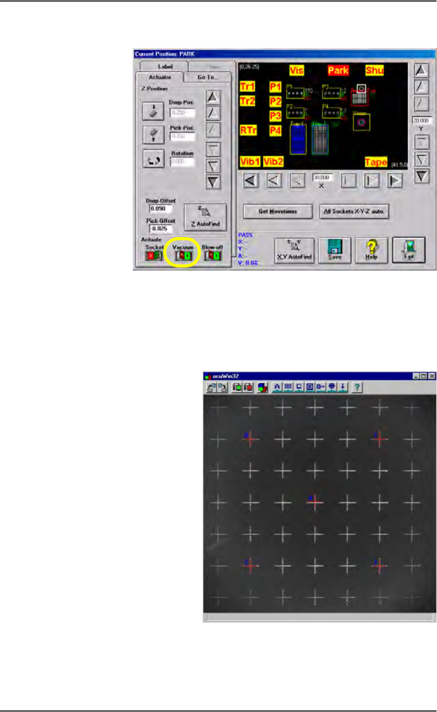
3f) Move the Red Cross Hairs-0, 1, 2 and 3 on top of the four White Cross
hairs in the four corners, as shown in Figure 5-54. Between each Red
Cross hair, there should be three White Cross hairs.
Figure 5-54—Cross hairs line up

Maintenance • Adjustments, Calibrations, and Functional Tests
PS288 Owner’s Manual 5—47
3g) On the Calib SysCalib window, set the World X and Y values as
shown in Figure 5-55. Press the Solve button. Then press the green tri-
angle to return to the Gantry window.
Figure 5-55—World values for X and Y
4. Adjust the Search Area—
4a) Manually remove the Vision Calibration Plate from the Vacuum Cup
nozzle. On the Gantry window, turn the Gantry Vacuum switch to OFF.
NOTE: In this example, Programmer 4 is used for illustration pur-
poses. Choose any programmer near the front of the PS288.
4b) Click P4. The PNP head will move to Programmer 4. Center the vac-
uum cup nozzle on the socket in Programmer 4. Use the X-axis and
Y-axis adjustment buttons on the Gantry window to center the PNP
head on the socket.
4c) Click Park to move the PNP head to the Park position. Manually place
a device in the socket of Programmer 4. Click P4 to move the PNP
head back to Programmer 4. Adjust the width of the Socket Actuator
ribs so that the ribs make contact with the socket top and yet are far
enough apart to be clear of the device when the device is picked.