PS288_OwnersMnl_PriorTo2009 - 第186页
Maintenance • Replacing Major Assemblies PS288 Owner’s Manual 5—51 Replacing the Pick And Place Head T o replace the PNP head: 1. Prepar e the system— 1a) From the Gantry window , move the PNP head to the front of the wo…
Maintenance • Replacing Major Assemblies
5—50 PS288 Owner’s Manual
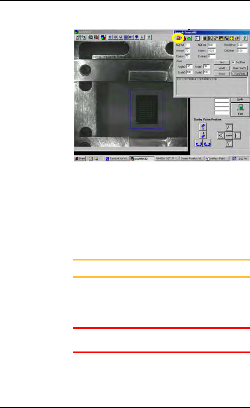
4i) On the Search Search dialog tool bar, click
a to hide Object dialog. See
Figure 5-60.
Figure 5-60—Click
a to hide Object dialog
4j) On the Gantry window, click P4 to return the PNP head to
Programmer 4. Right-click to place the device in the socket.
4k) On the Handler Computer, use Windows Explorer to copy the reference
vision file just modified (in this example, S273.prj).
4l) Paste a copy of S273.prj file to create Copy of S273.prj.
4m) Rename Copy of S273.prj to VisionTemplate.prj. This ensures that the
new vision calibration values are saved to the template used to teach
reference vision files.
This completes the process of calibrating the vision system.
NOTE: To teach a reference vision file, see “Teach the Reference
Vision File” on page 3-21
Replacing Major
Assemblies
The PS288 is a modular system that easily facilitates the removal and
replacement of most major assemblies. Basic instructions for their replace-
ment can be found in this section.
WARNING: Replacement of any mechanical assembly requires
machine recalibration to ensure proper placement of devices and
prevent damage to the PS288 or potential injury to personnel.
Maintenance • Replacing Major Assemblies
PS288 Owner’s Manual 5—51
Replacing the Pick And Place Head
To replace the PNP head:
1. Prepare the system—
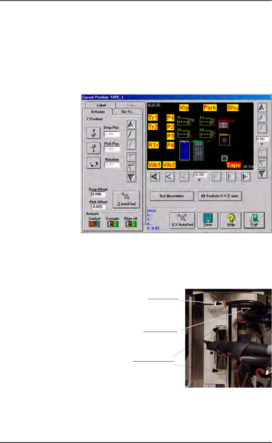
1a) From the Gantry window, move the PNP head to the front of the work
envelope so it can be easily reached. The Tape input location works
well. See Figure 5-61.
1b) Verify that the PS288 is shut down (see “Shut Down the System” on
page 3-12) and the main power switch is in the OFF position.
Figure 5-61— Move PNP head to Tape input location
2. Remove vacuum line and cable—
2a) Remove vacuum line by pulling the line gently while pushing the red
collar.
2b) Remove cable by loosening two screws (indicated in Figure 5-62).
Figure 5-62—Location of vacuum line and cable screws
Pull vacuum line
Push red collar
Loosen cable screws
Maintenance • Replacing Major Assemblies
5—52 PS288 Owner’s Manual
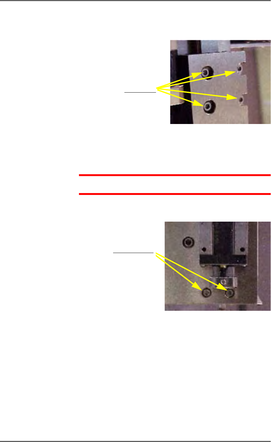
3. Swing Socket Actuator away from guide—
3a) Using a 2.5 mm Allen wrench, remove the four screws that hold the
Socket Actuator to the guide.
Figure 5-63—Removing four screws
3b) Swing the Socket Actuator away from the guide.
4. Remove old PNP head—
CAUTION: Hold the PNP head while removing the screws to pre-
vent the PNP head from falling.
4a) Using a 2.5 mm Allen wrench, remove the two lower screws that hold
the PNP head in place. See Figure 5-64.
Figure 5-64—Removing lower screws
4b) Using a 2.5 mm Allen wrench, remove the two upper screws that hold
the PNP head in place. See Figure 5-65.
Remove screws
Remove two screws