PS288_OwnersMnl_PriorTo2009 - 第194页
Maintenance • Fixing Failures PS288 Owner’s Manual 5—59 Check this: ) Make sure that the four 30-connector ribbon cables lab eled J1–J4 are connected to the I/O Controller I/ O Module from the PC A T Modul e. ) Make sure…

Maintenance • Fixing Failures
5—58 PS288 Owner’s Manual
Figure 5-69—Network hub with power on
Disabling a Programmer that Fails Self-test
If a programmer is not performing and you cannot correct the error, you can
continue to use other programmers after disabling the non-functional pro-
grammer.
To disable a programmer:
1. From the Setup window, click the Programmers tab.
2. Click the label for the failed programmer.
3. Click the black DISABLED button. The programmer label changes to
black and the programmer is disabled.
I/O Controller Problems
Problem:
• The I/O Controller green power LED doesn't light when the START
button is pressed.
Check this:
) Check the power source.
) Make sure that the front circuit breaker is on.
) Check that the loop back plug is inserted into the connector labeled
"Remote ON/OFF 24V" at the rear of the I/O Controller.
) Make sure that the top I/O Controller I/O module lid is screwed tight.
There is a safety interlock switch inside the lid.
) Check the fuse at the rear of I/O Controller; if you can hear the contac-
tor “clunk” internally, and the START switch lights, this indicates the
24 VAC low voltage loop circuit works, but the 5VDC supply is not
working.
Problem:
• The I/O Controller shuts off by itself after a while.
Check this:
) Check for power surges causing the circuit breakers to open.
Problem:
• An output relay is not activating, and its corresponding green LED is
off at the front panel.

Maintenance • Fixing Failures
PS288 Owner’s Manual 5—59
Check this:
) Make sure that the four 30-connector ribbon cables labeled J1–J4 are
connected to the I/O Controller I/O Module from the PC AT Module.
) Make sure that the direction selection at that port’s jumper patch is not
missing or set for an input type of port.
Problem:
• An output relay is not activating, but the green LED on the front panel
indicates that it should be.
Check this:
) Check the voltage selection at that port’s jumper patch.
) Check the fuse on the case of the solid state relay.
Air Pressure Problems
Problem:
• There is no main air pressure.
Check this:
) Make sure that the main air switch on the input panel is in the ON posi-
tion.
) Check the fuse in the I/O Controller connector.
) Make sure that the sensor switch in the pneumatic control panel (+24V)
is on.
) Check the pico fuse in the sensor/dump bank inside of the I/O Control-
ler.
Problem:
• There is no or low vacuum on the PNP probe.
Check this:
) Make sure that there is voltage at the sensor mounted on the PNP head.
) Check the vacuum/blow-off solenoid.
) Check solenoid 4 (vacuum and blow-off) mounted on top of manifold.
) Check solenoid 1 (up/down) mounted of top of manifold.
) Check the PNP head probe to determine if it is clogged. Clean if neces-
sary.
Servo Motor Problems
When you need to reload the software on the motion controller card of the
PS288, complete this procedure:
You will need Software MC_DSP_XP (Windows version)
1. Prepare the system—
1a) Open the door on the right side of the PS288.
1b) Examine the Y-axis and X-axis servo motor amps.
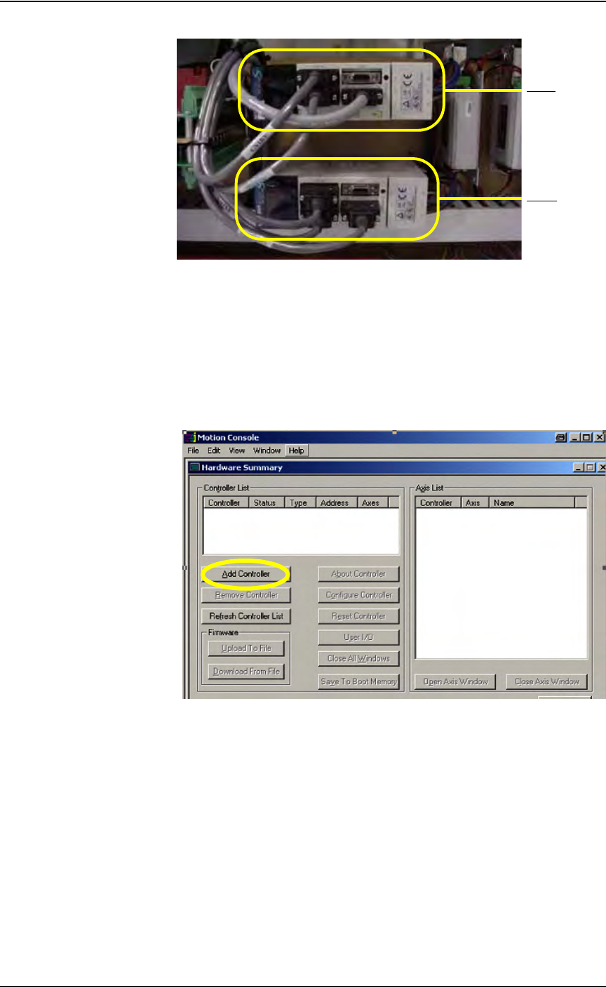
Maintenance • Fixing Failures
5—60 PS288 Owner’s Manual
Figure 5-70—Y-axis and X-axis servo motor amps
2. Launch Windows Explorer—
2a) Go to C:\Install\Setup.
2b) Run MC_DSP_XP.
3. Add controller—
3a) If your window shows no controller in the Controller List field (see
Figure 5-71), click Add Controller.
Figure 5-71—No controller in list box
3b) In the Add Controller window, type MEI. Click OK. See Figure 5-72.
Y- ax i s
X-axis