PS288_OwnersMnl_PriorTo2009 - 第197页
Maintenance • (Optional) Tape Output System 5—62 PS288 Owner’s Manual Figur e 5-74—Select file 4d) Click Ye s to replace the firmware on co ntroller “MEI,” as shown in Figur e 5-75 . Figur e 5-75—Replace firmwar e 5. Com…
Maintenance • Fixing Failures
PS288 Owner’s Manual 5—61
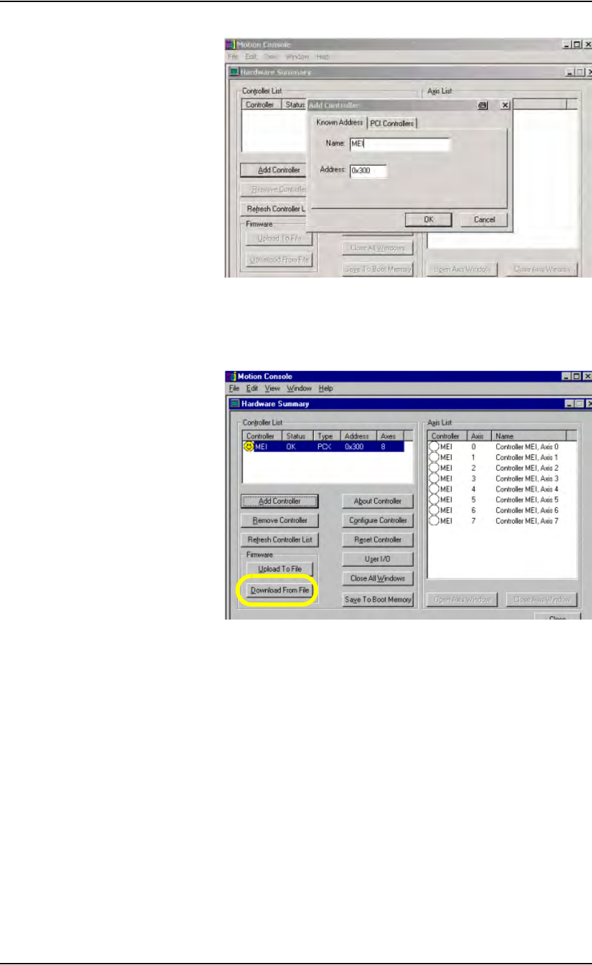
Figure 5-72—Add controller
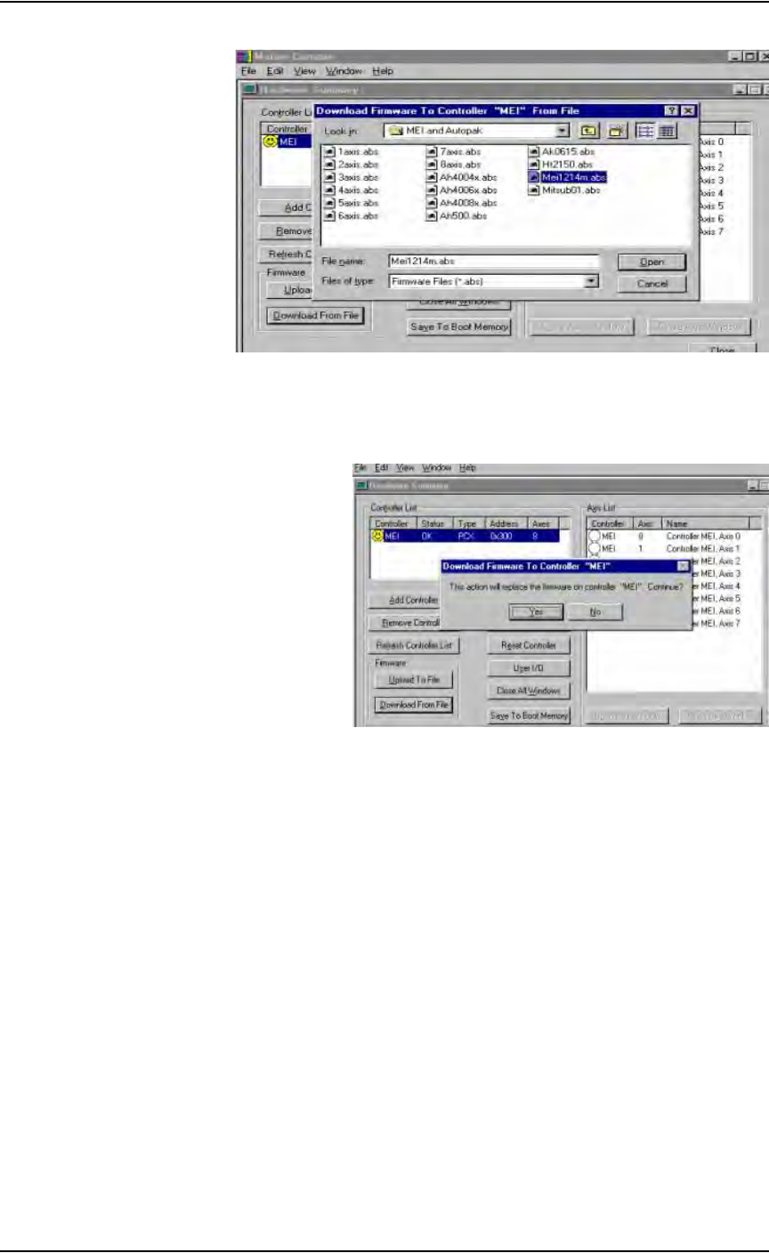
4. Download file—
4a) On the Hardware Summary window, select Download From File. See
Figure 5-73.
Figure 5-73—Download from file
4b) Select the correct software file for the type of servo motor installed. For
Mitsubishi motors, select MEI1214M.ABS.
4c) Click Open.
Maintenance • (Optional) Tape Output System
5—62 PS288 Owner’s Manual
Figure 5-74—Select file
4d) Click Ye s to replace the firmware on controller “MEI,” as shown in
Figure 5-75.
Figure 5-75—Replace firmware
5. Complete process—
Press Alt-X to exit.
The motion controller card now has the new software loaded and the process
is complete.
(Optional) Tape
Output System
Cleaning the Pressure Seal Tape Output System
Pressure seal tape output systems require cleaning to prevent problems with
breaking the carrier tape or tearing the carrier tape sprocket holes. The clean-
ing process removes adhesive build up from the cover tape application roll-
ers and the drive sprocket top pressure idler wheel.
To clean the pressure seal tape output system:
TOOLS REQUIRED: Shop towel and alcohol or commercial alcohol wipes.
Maintenance • (Optional) Tape Output System
PS288 Owner’s Manual 5—63
1. Prepare the system—
1a) Switch on the PS288 and start the AH500 software on the Handler
Computer.
1b) Load a job that requires the use of the tape output Controller.
1c) Start the job and let the AH500 complete its startup process.
1d) Switch on the tape output Controller.
2. Configure the tape output Controller—
2a) Configure the tape output Controller by setting the following:
•From the Setup menu, reset Count Stop to desired amount.
•From the Setup menu, reset Present Count to zero.
•From the Setup menu, select the desired carrier tape pitch from the
pitch selection menu. The pitch selection choices are 4, 8, 12, 16, 20,
24, 28, 32, and other.
•From the Advance menu, set the number of pockets to advance to 1.
• From the Speed menu, set the advance speed from 40 to 100 depending
on the carrier tape width and device size. Smaller devices and narrower
tape widths run best with slower speeds, in the range 40 to 60. Higher
speeds may cause the devices to be dislodged from the pockets or may
cause the sprocket holes on the tape to rip out. A recommended speed
is 60 to prevent carrier tape advance problems and breakage.
•From the Jog menu, jog the carrier tape forward to line up the pocket
with the PNP head.
•From the Mode menu, press option 3 (PSA) for pressure seal cover
tape.
•From the Run menu, place the unit in the run mode. The run window
displays all the selected setup parameters.
2b) Verify all settings for accuracy.
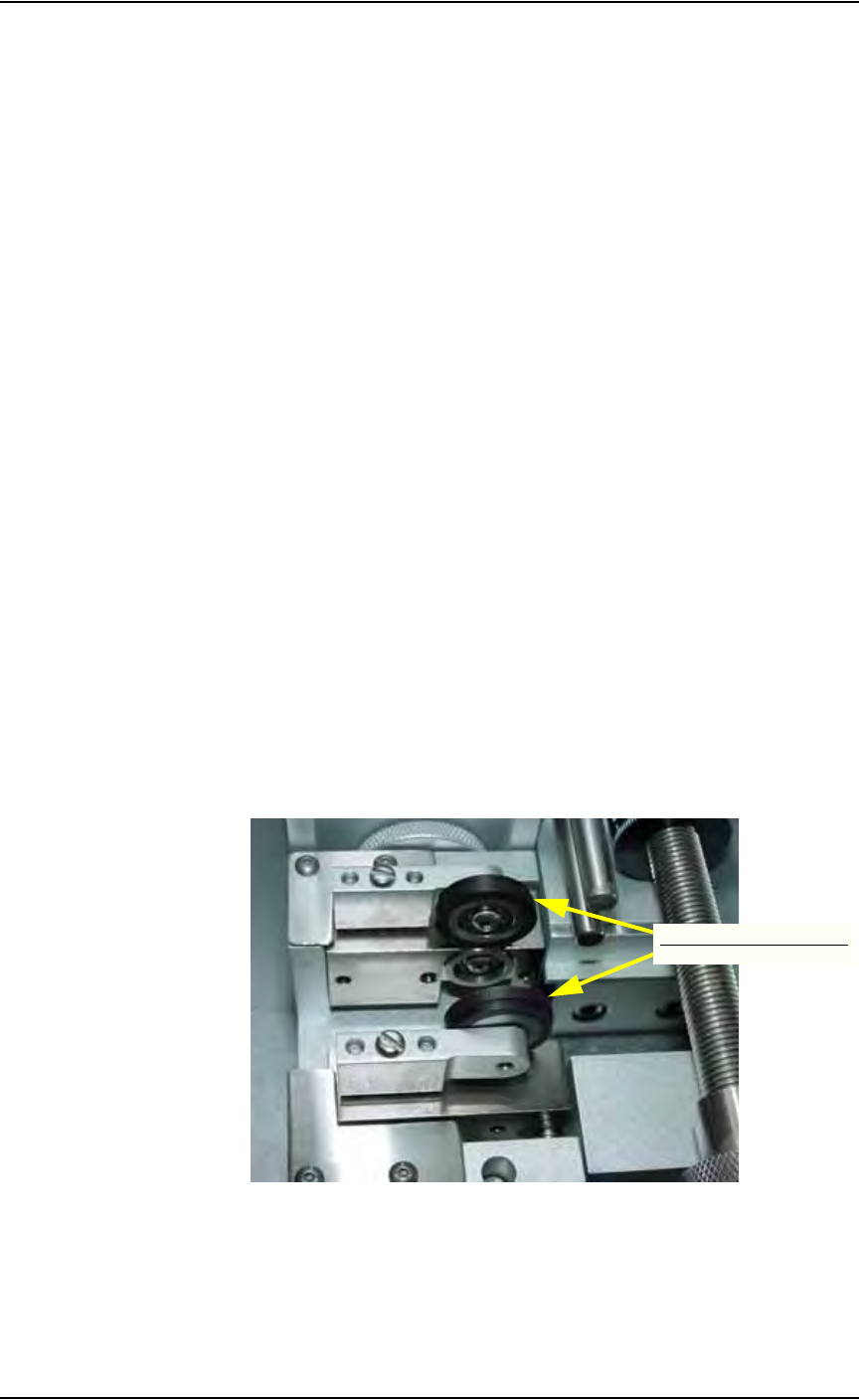
3. Inspect the cover tape application rollers—
Visually inspect the cover tape application rollers (see Figure 5-76) for
build up of adhesive from the cover tape.
Figure 5-76—Cover tape application rollers
4. Inspect drive sprocket idler and rubber O-rings—
Visually inspect the drive sprocket top idler and rubber O-rings for any
build up of adhesive from the cover tape. See Figure 5-77.
Cover tape application rollers