PS288_OwnersMnl_PriorTo2009 - 第199页
Maintenance • (Optional) Tape Output System 5—64 PS288 Owner’s Manual Figur e 5-77—Idler pressur e wheel and O-rings 5. Remove adhesive build up fr om drive sprocke t idler and O-rings— 5a) Gently remove the O -rings fro…
Maintenance • (Optional) Tape Output System
PS288 Owner’s Manual 5—63
1. Prepare the system—
1a) Switch on the PS288 and start the AH500 software on the Handler
Computer.
1b) Load a job that requires the use of the tape output Controller.
1c) Start the job and let the AH500 complete its startup process.
1d) Switch on the tape output Controller.
2. Configure the tape output Controller—
2a) Configure the tape output Controller by setting the following:
•From the Setup menu, reset Count Stop to desired amount.
•From the Setup menu, reset Present Count to zero.
•From the Setup menu, select the desired carrier tape pitch from the
pitch selection menu. The pitch selection choices are 4, 8, 12, 16, 20,
24, 28, 32, and other.
•From the Advance menu, set the number of pockets to advance to 1.
• From the Speed menu, set the advance speed from 40 to 100 depending
on the carrier tape width and device size. Smaller devices and narrower
tape widths run best with slower speeds, in the range 40 to 60. Higher
speeds may cause the devices to be dislodged from the pockets or may
cause the sprocket holes on the tape to rip out. A recommended speed
is 60 to prevent carrier tape advance problems and breakage.
•From the Jog menu, jog the carrier tape forward to line up the pocket
with the PNP head.
•From the Mode menu, press option 3 (PSA) for pressure seal cover
tape.
•From the Run menu, place the unit in the run mode. The run window
displays all the selected setup parameters.
2b) Verify all settings for accuracy.
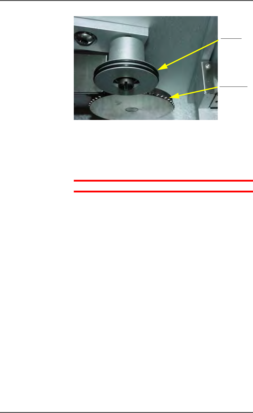
3. Inspect the cover tape application rollers—
Visually inspect the cover tape application rollers (see Figure 5-76) for
build up of adhesive from the cover tape.
Figure 5-76—Cover tape application rollers
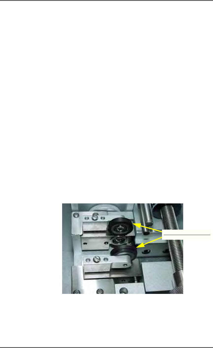
4. Inspect drive sprocket idler and rubber O-rings—
Visually inspect the drive sprocket top idler and rubber O-rings for any
build up of adhesive from the cover tape. See Figure 5-77.
Cover tape application rollers
Maintenance • (Optional) Tape Output System
5—64 PS288 Owner’s Manual
Figure 5-77—Idler pressure wheel and O-rings
5. Remove adhesive build up from drive sprocket idler and O-rings—
5a) Gently remove the O-rings from the drive sprocket idler. Avoid damage
to the O-rings.
5b) Using a shop towel damp with alcohol or a commercial alcohol wipe,
remove all adhesive from O-rings.
CAUTION: Wipe gently to avoid breaking the O-rings.
5c) With the O-rings removed from the idler, clean the top idler using the
shop towel and alcohol or alcohol wipes.
5d) Once all adhesive has been removed from the O-rings and idler wheel
and the alcohol has dried, reinstall the O-rings on the top idler wheel.
6. Remove adhesive build up from the cover tape application roll-
ers—
6a) Using a shop towel and alcohol or alcohol wipes, clean the adhesive
build up from the cover tape application rollers. Hold the alcohol towel
or wipe on the roller and spin the roller until the entire roller has been
cleaned.
6b) Repeat procedure for the other application roller.
7. Check pressure of cover tape application roller—
7a) Advance the carrier tape with the cover tape through the application
rollers using the manual advance pedal. Advance enough pockets to
correctly align the cover tape on the carrier tape.
7b) Perform a "peel back" test by peeling the cover tape from the carrier
tape. Note how well the cover tape adhered to the carrier tape. Perform
a "twist" test by giving the tape a slight twist. Note if the cover tape
detaches from the carrier tape.
7c) If either test produces loose cover tape, increase the application roller
pressure by screwing in on the roller mounting screw and spring
assembly.
7d) If both tests look acceptable, visually inspect the sealed carrier tape for
adhesive that may have been squeezed out during application. If adhe-
sive is visible, the application roller pressure is too high. Decrease the
Drive sprocket
O-rings (2)
Maintenance • (Optional) Tape Output System
PS288 Owner’s Manual 5—65
application roller pressure by screwing out on the roller mounting
screw and spring pressure assembly.
The cleaning procedure for the pressure sealing tape output system is now
complete.
Troubleshooting and Adjusting Sensors in the Tape
Output System
The tape output system contains sensors that detect these fault conditions:
• A device is jammed in the carrier tape (Device Jam Sensor)
• No cover tape is on the reel (Cover Tape Sensor)
• Carrier tape is not properly inserted in the Carrie Tape Input Guide
(Carrier Tape Sensor)
• A pocket in the carrier tape is empty (Pocket Empty Sensor)
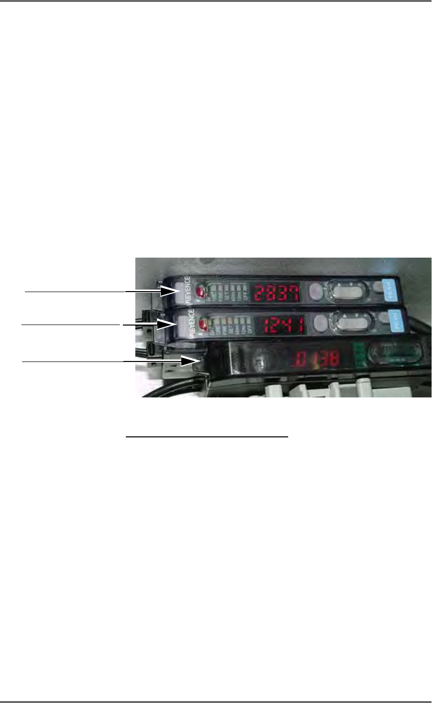
When the AH500 software displays the error message “Tape Out Unit,” one
of the tape output system sensors has been triggered. The most likely sensors
to trigger are the Device Jam and Carrier Tape sensors. See Figure 5-78.
Figure 5-78—Sensor controllers
Device Jam Sensor and Controller
The Device Jam sensor detects when a device is not properly seated in the
pocket. This sensor is located on the Adjustable Loading Track immediately
before the carrier tape enters the Carrier Tape Guide.
When the Device Jam sensor is triggered, an orange LED is illuminated in
the Device Jam Sensor Controller (1 in Figure 5-78).
Problem:
• Error message "Tape Out Unit" displays and an orange LED is illumi-
nated in the Device Jam Sensor Controller.
Check this:
) Use a vacuum tool to seat the device in the carrier tape pocket.
) Re-seat the carrier tape in the Adjustable Loading Track.
) Use air to blow any debris out of the Device Jam sensor path.
) Adjust the Device Jam Sensor Controller. See below.
1. Device jam sensor controller
2. Cover tape sensor controller
3. Carrier tape sensor controller