PS288_OwnersMnl_PriorTo2009 - 第20页
Introduction • Software an d User Interface Components 1—10 PS288 Owner’s Manual W ARNING: Pressing an E-S top butt on stops motion of the gantry and PNP head only . It does not remove power from the PS288 or the Option …

Introduction • Safety Systems
PS288 Owner’s Manual 1—9
be disposed of in accordance with government hazardous waste
regulations.
Input panel (not shown)—
Fittings on this panel, located on the rear of the PS288, allow for the
attachment of air (used to generate the necessary vacuum and posi-
tive-pressure air to manipulate devices and operate optional assem-
blies) and power. See Figure 2-2.
Circuit breakers (not shown)—
Circuit breakers located on the input panel provide circuit protection
and a source of power for the various assemblies in the PS288.
Main power switch (not shown)—
Located on the input panel, the main power switch is used to switch
primary power for the PS288.
Input/Output Options and Combinations
PS288 input and output options include static tray (manual), automatic tray
feeder, tube, and tape.
Standard configuration for the PS288 is static tray input/static tray output.
However, any combination of input and output options may be used. For
example, the PS288 can be configured with automatic tray feeder input com-
bined with tube output, or tape input combined with static tray output, or
tube input combined with tape output, etc.
Safety Systems
The PS288 has several safety systems to prevent personal injury and
machine damage. These systems include:
1. Emergency stop (E-Stop) buttons—
Two large, red Emergency Stop buttons are located near the top of the
PS288, one on either side of the machine. The buttons are easily
reached in an emergency. When an E-Stop button is pressed, the gantry
and PNP head stop moving immediately.
.
Figure 1-3—Emergency stop button
Introduction • Software and User Interface Components
1—10 PS288 Owner’s Manual
WARNING: Pressing an E-Stop button stops motion of the gantry
and PNP head only. It does not remove power from the PS288 or
the Option Bay (if installed).
To restart the system, turn the E-Stop button clockwise (follow the
direction of the arrows on the button) until it springs back to its full
height. Follow onscreen messages to resume operation.
2. Safety shields and interlocks—
During operation, when the high-speed PNP head is processing
devices, the clear plastic shields around the system are closed to protect
personnel from injury.
WARNING: The high speed and force behind a moving gantry
will expose anyone working inside the operating envelope to seri-
ous bodily injury. When working within the machine, moving the
PNP head must be the responsibility of only one qualified individ-
ual. All other personnel near the system must stay clear of the
operating envelope and any machine controls to prevent injury to
the person working within the PS288. Never operate the PS288
with any interlock bypassed.
CAUTION: Do not use solvents such as acetone, lacquer thinner,
mineral spirits, isopropyl alcohol, or any type of abrasive com-
pound on the safety shield surfaces. Use of these products will dam-
age the safety shield surfaces and reduce visibility within the
operating area.
Software and
User Interface
Components
During programming operations, the PS288 is controlled using the key-
board, touchpad, or touch screen, and two software interfaces (TaskLink and
AH500). The software components reside in the Handler Computer on the
PS288.
The PS288 is a complete system with various subsystems within it, such as
the robotics system, power supplies, programmers, and Handler Computer.
In order to operate properly, the PS288 must remain intact.
The Handler Computer, with an additional Network Interface Card (NIC),
can communicate with a corporate network. The primary logon for the Han-
dler Computer will be MS Client.
Customer-supplied antivirus software can be installed on the Handler Com-
puter. However, the antivirus software should not be scheduled to execute
during a Job run. Instead, execute the antivirus software after the PS288 is
first started and before a Job is run.
Introduction • Software and User Interface Components
PS288 Owner’s Manual 1—11
In addition, customer-supplied Statistical Process Control software can be
installed on the Handler Computer. See “Statistical Process Control Software
(SPC)” on page 3-50 for more information.
The PS288 should never have other software added unless instructed to do
so by Data I/O Customer Support.
CAUTION: Adding software to the PS288 can cause damage
and/or cause it to operate improperly. Adding software without spe-
cific instruction from Data I/O Customer Support will void the war-
ranty and may incur service charges.
CAUTION: Windows system parameters and network parameters
should not be changed unless instructed to do so by Data I/O Cus-
tomer Support. Changing Windows or network system parameters
can cause failure and/or damage to these systems or cause
improper programming.
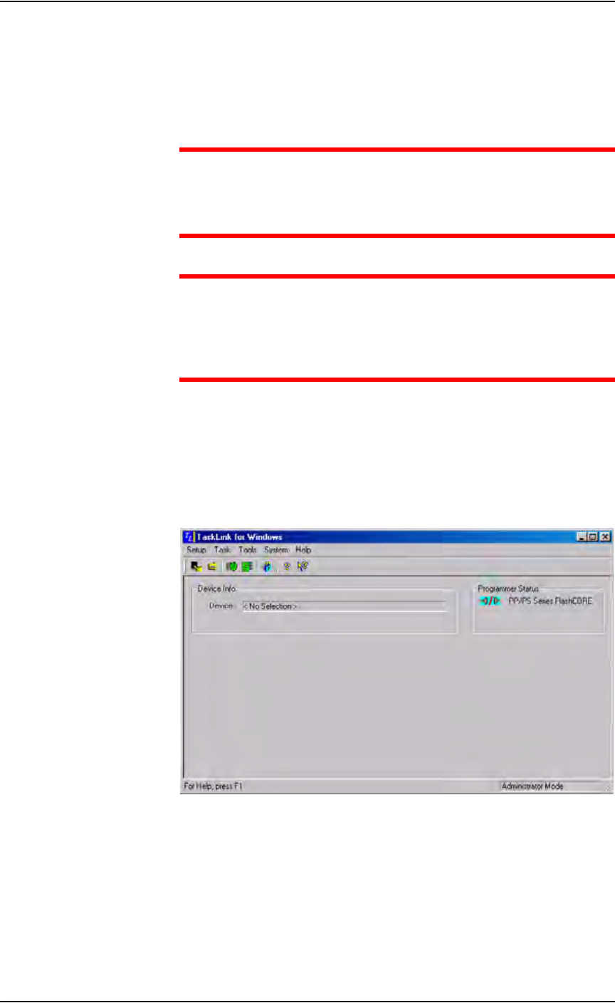
TaskLink Interface
Data I/O’s user interface is TaskLink
™
for Windows
®
. TaskLink uses a
Microsoft
®
Windows
®
-based system for Task creation and analysis and oper-
ates from the Handler Computer. TaskLink is used to create jobs to run on
the PS288. Figure 1-4 shows the TaskLink main screen.
Figure 1-4—TaskLink main screen