PS288_OwnersMnl_PriorTo2009 - 第202页
Maintenance • (Optional) Label Printin g System PS288 Owner’s Manual 5—67 Carrier T ape Sensor and Controller The Carrier T ape sensor detects when car rier tape is not inserted in the Car- rier T ape Input Guide. When t…

Maintenance • (Optional) Tape Output System
5—66 PS288 Owner’s Manual
Adjusting the Device Jam Sensor Controller
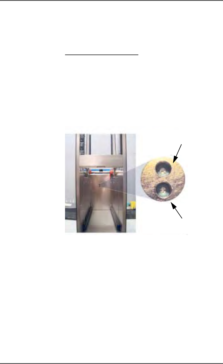
1. Fiber optic cables—
Set the fiber optic cables by unscrewing the hex screw and rotating the
cable until the light shines through and the LED value reads as high as
possible (typically around 200).
2. Output Mode 1—
2a) There are two output modes: Output Mode 1 and Output Mode 2. Set to
Output Mode 1 by turning the jog switch to the (+) or (-) side. The
blinking cursor bar alternates between Output 1 and Output 2.
2b) Press the jog switch to Output Mode 1. Change it from "Lnon" to
"Dnon" by turning the jog switch to either (+) or (-) side.
NOTE: Lnon = Light ON and Dnon = Dark ON
2c) Turn the mode selection switch to "SET." The current threshold value
is displayed. Re-set the current threshold value to 90 by turning the jog
switch to either (+) or (-) side to obtain the desired threshold value.
2d) Repeat Step 2a through Step 2c for Output Mode 2.
3. RUN—
When both Output Mode 1 and Output Mode 2 are set, set MODE
switch to "RUN." For normal operation, both fault LEDs should be off.
Cover Tape Sensor and Controller
The Cover Tape sensor detects when there is no cover tape on the reel. When
the Cover Tape sensor is triggered, a red LED is illuminated in the Cover
Tape Sensor Controller (2 in Figure 5-78).
Problem:
• Error message "Tape Out Unit" displays and red LED is illuminated in
the Cover Tape Sensor Controller.
Check this:
) Replace empty cover tape reel.
) Adjust the Cover Tape Sensor Controller if the reel still contains cover
tape. See below.
Adjusting the Cover Tape Sensor Controller
1. Ensure that the Output Selector Switch is set to D.ON.
2. Install a roll of cover tape on the unit.
3. Press and release the "SET" button. The Calibration Indicator, [SET]
LED bar, will light up.
4. Remove the cover tape.
5. Press and release the "SET" button.
NOTE: If an error occurs or the sensor fails to detect the cover
tape after switching from a different type of cover tape, then the
Cover Tape sensor may need to be re-taught to sense that particular
type of cover tape.

Maintenance • (Optional) Label Printing System
PS288 Owner’s Manual 5—67
Carrier Tape Sensor and Controller
The Carrier Tape sensor detects when carrier tape is not inserted in the Car-
rier Tape Input Guide. When the Carrier Tape sensor is triggered, a red LED
is illuminated on the Carrier Tape Sensor Controller (3 in Figure 5-78).
Problem:
• Error message "Tape Out Unit" displays and the red LED on the Carrier
Tape Sensor Controller is illuminated.
Check this:
) Replace the carrier tape reel if it is empty.
) Adjust the Carrier Tape Sensor Controller if the reel still contains car-
rier tape. See below.
Adjusting the Carrier Tape Sensor Controller
1. Set switches—
Ensure that the switches are set as shown:
MODE = D.ON
ALM = OUT
TIMER = OFF
2. Fiber optic sensor—
2a) Adjust the open end of the fiber optic sensor cable so that the green
LED illuminates when the carrier tape is present.
2b) Adjust the open end of the fiber optic sensor cable so that the red LED
illuminates and a buzzer sounds when carrier tape is not present.
Pocket Empty Sensor
The Pocket Empty sensor verifies that a pocket is empty as the carrier tape
approaches the Tape Output PNP head location. The sensor shines a fiber
optic light through the small hole in the center of the pocket. If the fiber
optic light is blocked, for example by a device in a pocket, the sensor is trig-
gered. There is no controller that displays this condition.
Problem:
• Error message "Tape Out Unit" displays and no other sensor has trig-
gered an LED.
Check this:
) Adjust the Pocket Empty Sensor. Using an Allen wrench, loosen the
two cap screws that hold the sensor bracket. Move the bracket in the
Y-axis direction until the fiber optic light shines through the hole in the
center of the pocket. Tighten the screws.
(Optional) Label
Printing System
For detailed information on completing regular maintenance, replacing
assembly units, making mechanical alignments and adjustments, and trou-
bleshooting the label printing system, see the Apollo 1 Service Manual that
came with your label printing system.
Maintenance • (Optional) Automatic Tray Feeder
5—68 PS288 Owner’s Manual
(Optional)
Automatic Tray
Feeder
The TF20 automatic tray feeder is designed to keep a tray from stopping too
abruptly when it reaches the end of the conveyor nearest the PS288 or the
end of the conveyor nearest the TF20. (Abrupt stops can cause devices to
move on the tray.) You may need to adjust the conveyor speed if trays are
stopping too abruptly.
Conveyor Speed Adjustments
Two sensors control the speed of the conveyor.
• The "Return to Stack" sensor is located near the end of the conveyor
closer to the TF20 stack. When the leading edge of the tray passes this
sensor, the conveyor shifts to slow speed operation.
• The “Place in PS288” sensor is located near the end of the conveyor
closer to the PS288. When the leading edge of a tray passes this sensor,
the conveyor shifts to slow speed operation.
When either sensor is triggered, the conveyor shifts to slow speed operation.
The speed of the conveyor is adjusted with the potentiometers shown in Fig-
ure 5-79.
Figure 5-79—Conveyor speed potentiometers
To adjust conveyor speed:
1. Press the Stop button on the TF20.
2. Adjust “Return to Stack” or “Place in PS288” potentiometer:
• To increase conveyor speed, turn potentiometer clockwise
• To decrease conveyor speed, turn potentiometer counterclockwise
3. Press the Reset button on the TF20.
"Return to Stack" potentiometer
(turn clockwise to increase speed)
“Place in PS288” potentiometer
(turn clockwise to increase speed)