PS288_OwnersMnl_PriorTo2009 - 第212页
PS288 Owner’s Manual Index—1 A Address change -iii Administra tor Functions 3-20 to 3-56 create a job 3-20 teach reference vision file 3-21 teach package file 3-35 create a label printing file 3-65 create a laser marking…
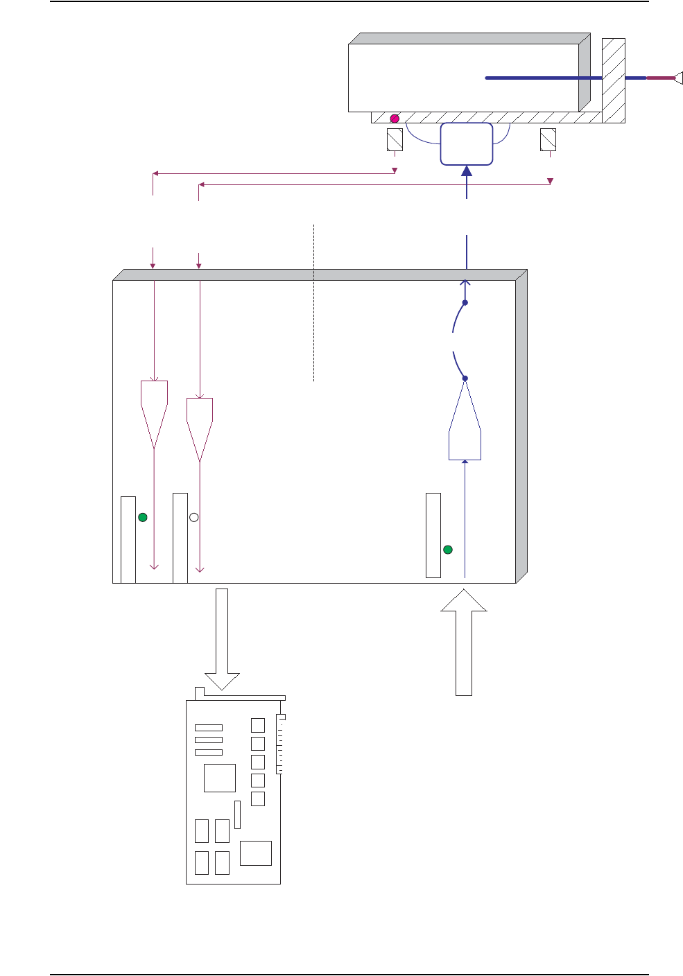
Appendix C
PS288 Owner’s Manual C-3
Socket Opener
UP
Signal
I/O Controller
PIO-96W
Bi-Directional Digital I/O
Board
in Handler Computer
PNP Head
Solenoid
1SV1
(Coil)
Up
Down
Socket Opener
DOWN
Signal
Output
Command
Up
Sensor
Down
Sensor
Socket
Opener
Socket Opener Ribs
Outputs to Coils / Solenoids
Inputs from Sensors
Socket Sensed
UP
Socket Sensed
DOWN
Port-1 Bit-1
Port-1 Bit-2
Port-5 bit-0
Hose
Air Hose
Opto Isolator
Solid State Relay
Opto Isolator
Opto Isolator
Socket
UP
Command
I/O Controller Input Ports (Port-1 to Port-4)
Handler Computer Interface to I/O Controller and Signal Conditioning Example
Fuse
I/O Controller Output Ports (Port-5 to Port-9)
I/O Controller and Signal Condition-
ing Example

PS288 Owner’s Manual Index—1
A
Address change -iii
Administrator Functions 3-20
to 3-56
create a job 3-20
teach reference vision file 3-21
teach package file 3-35
create a label printing file 3-65
create a laser marking file 3-57
create data file from master device 3-56
maximize programming yields 3-53
monitor daily operation logs 3-55
monitor statistics 3-50
AH400
configuring for label printing 2-25
configuring for tape input 2-10
configuring for tape output 2-15
configuring for tube feeder 2-9
description 1-13
installing service releases 5-29
launching from TaskLink 3-4
user interface example 1-14
viewing package statistics 3-50
WinAH400.ini file 1-13
Air
checking and replacing input air filter 5-5
connecting external air line 2-2
Antivirus Software 1-11
Automatic Tray Feeder
conveyor speed adjustments 5-68
description 1-8
maintenance monthly 5-12
maintenance weekly 5-5
Automatic Tray Feeder TF20
operating 3-18
Automatic Tray Feeder TF30
operating 3-19
Axes, motion and direction
X, Y, Z and R 1-2
B
Basic Operations 1-3
Blow-Off
adjusting 5-36
description 1-5
C
Calibrate FlashCORE Programmers 5-27, 5-41
Carrier Tape Sensor 5-67
Circuit Breakers
description 1-10
system theory 4-1
Computer Vision System
description 4-7
Conveyor Speed
adjusting on Automatic Tray Feeder 5-68
Cover Tape Sensor 5-66
Customer Support Offices -ii
D
Daily Operation Logs, monitoring 3-55
Data File
creating from a master device 3-56
description 3-20
Data I/O
customer support offices -ii
Device Jam Sensor 5-65
Devices
handling 1-24
Disabling
clearing disabled programmer status 3-13
programmer 5-58
E
Electrical Input Requirements 2-3
Emergency
stop and restart 3-10
Emergency Stop (E-Stop) Buttons
restarting after using 1-10
End a Job 3-12
Errors
while teaching package file 3-47
ESD
operator grounding plug 1-6
precautions 1-24
F
Facilities Required
power and air 1-16
Index

Index
Index—2 PS288 Owner’s Manual
Feeder Unit
aligning pick point 2-14
setting pitch 2-13
teaching location for package file 3-46
Filter
cleaning input air filter 5-5
FlashCORE Programmers
calibrating 5-27, 5-41
internal structure 4-2
preselecting for Job 3-15
replacing assembly 5-53
Fume Extractor
description 1-8
filter replacement intervals 1-22
replacing all filters 5-24
replacing pleated filter 5-18
replacing pre-filter 5-8
G
Gantry
description 1-4
system theory 4-6
Gantry Lead Screws
grease fittings 5-23
Get Movetimes 3-46
H
Handler Computer
overview 1-6
system description 4-4
Handler User Interface
AH400 1-13
TaskLink 1-12
I
I/O Controller
overview 1-6
system description 4-1
Input Panel
description 1-10
Input/Output Modules
automatic tray feeder 2-7
standard and optional combinations 1-10
static tray 2-5
tape 4-8
tray 4-9
tube 2-7, 4-8
Interface Cable
connecting to tape input feeder 2-12
K
Keyboard and Touchpad
description 1-6
system theory 4-5
L
Label Printing
creating file 3-65
editing winAH400.ini file 2-25
label type 3-65
setting up 2-25
to 2-26
system description 4-9
Laser Filters
determining contents 1-22
handling and storage 1-23
replacement intervals 1-22
replacing all 5-24
replacing pleated filter 5-18
replacing pre-filter 5-8
Laser Marking File
creating 3-57
to 3-64
editing image file text 3-59
loading image file 3-60
template.mkh default settings 3-59
verifying proper laser operation 3-62
Laser Marking System
description 4-10
first time installation 2-27
safety interlock description 1-19
safety interlock locations 1-19
safety labels 1-20
set up 2-27
specifications 1-18
Light Tower 4-5
colors 3-13
description 1-4
monitoring 3-13
M
Main Power Switch
description 1-10
Main Power Systems 4-1
Maintenance
interval table 5-2
Marking System
description 1-7
Master Device
creating data file from 3-56