PS288_OwnersMnl_PriorTo2009 - 第24页
Introduction • Software an d User Interface Components 1—14 PS288 Owner’s Manual the PNP head to that location in the work envelope. When selected, the yel- low position lab el turns red. In Fi gur e 1-7 , the Park label…
Introduction • Software and User Interface Components
PS288 Owner’s Manual 1—13
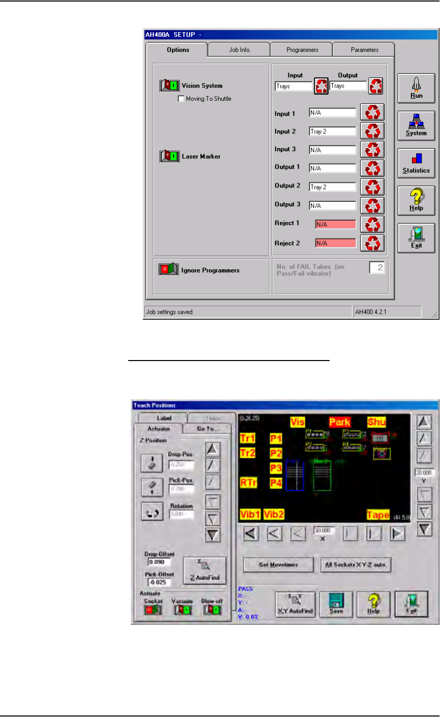
Figure 1-6—AH500 user interface example
Understanding the AH500 Gantry Window
The AH500 Gantry window displays important information about the work
envelope of the PS288.
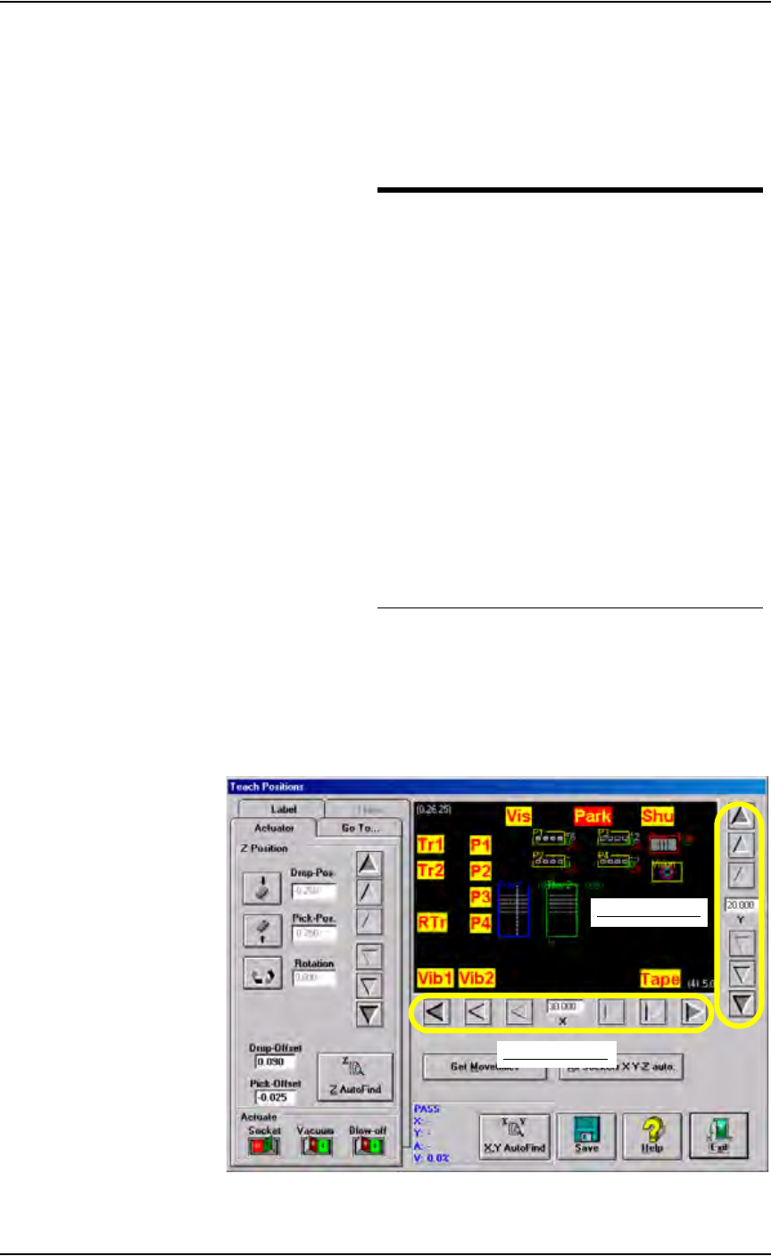
Figure 1-7—Gantry window
The yellow position labels on the Gantry window represent locations in the
work envelope. Clicking a yellow position label (for example, Tr1) moves
Introduction • Software and User Interface Components
1—14 PS288 Owner’s Manual
the PNP head to that location in the work envelope. When selected, the yel-
low position label turns red. In Figure 1-7, the Park label (red) is selected
and the PNP head is at the Park position.
Figure 1-8 lists position labels and their locations in the work envelope.
Figure 1-8—Label and locations
Also on the AH500 Gantry window are adjustment arrows for the X-axis and
Y-axis. Clicking an arrow moves the PNP head the given distance in the
direction chosen. From the inside working outward, the arrows adjust the
position ±0.001, 0.010, and 0.100 inches respectively. See Figure 1-9.
Figure 1-9—Adjustment arrows for X- and Y-axes
Label Location in work envelope
Tr1 Tray 1
Tr2 Tray 2
RTr Reject Tray
P1 Programmer 1
P2 Programmer 2
P3 Programmer 3
P4 Programmer 4
Vib1 Tube Vibrator 1
Vib 2 Tube Vibrator 2
Vis Vision System
Park Park
Shu Shuttle Transfer
Tape Tape Input
X-axis adjustment
Y-axis adjustment
Introduction • Required Facilities for Operation
PS288 Owner’s Manual 1—15
Laser Interface
The Laser interface is used to create parameters required for laser jobs and
start laser marking. The software resides on the Laser Computer in the laser
marking system located in the Option Bay. The Laser Computer operates
using the Microsoft
®
Windows XP operating system.
The Laser Computer is accessed through the keyboard by pressing
CTRL-CTRL, typing "B" and pressing ENTER. The Laser interface is dis-
played on the monitor and controlled through the keyboard and touchpad.
The touch screen does not work while in Laser Computer mode. To return to
the Handler Computer, press CTRL-CTRL, type "A" and press ENTER.
When the laser marking system is set up and initialized, it receives com-
mands from the AH500 software initiating the marking sequence. See Fig-
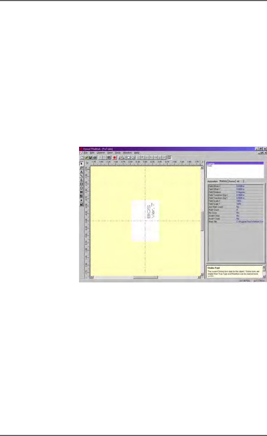
ure 1-10 for an example of the laser interface configuration window. More
information about the laser interface follows in Chapter 2—Set Up and
Chapter 3—Operation.
Figure 1-10—Laser computer interface example
Required
Facilities for
Operation
The PS288 is a self-contained unit that creates most of its own power supply
voltages and signals required for proper operation. Power requirements are
208–240 VAC, 50/60 Hz, single phase electrical power. Air requirements are
clean, dry, oil-free air, input rated between 620 and 827 kiloPascals (90 to
120 PSI) from an industrial grade compressor with a tank of sufficient size to
maintain constant air pressure at 85 liters per minute (3 Standard Cubic Feet
per Minute).
Precautions for
Safe Operation
The PS288 has many safety features designed to make the system safe and
efficient to operate. The system can be dangerous if the safety precau-
tions and features in the manual are ignored.