PS288_OwnersMnl_PriorTo2009 - 第36页
Set Up • Making the Necessary Connections 2—2 PS288 Owner’s Manual Pneumatic Input and Controls The PS288 requires clean, dry , oil-free air from an industrial grade compres- sor . The compressor ’ s tank should be of su…
PS288 Owner’s Manual 2—1
Chapter
2
2Set Up
PS288 installation is performed by Data I/O service personnel or an autho-
rized distributor. The PS288 requires an operating location and two external
facilities (power and air).
The system arrives in a wooden crate. After ensuring that there is no damage
to the exterior of the crate, the installer removes the crate and inspects for
damage that may have occurred during shipping. If there appears to be no
damage, the PS288 is unbolted from the shipping pallet and moved to the
floor.
The operating location for the PS288 must:
• allow at least one meter (36 inches) of area around its perimeter for
opening and removing panels as well as repairing and replacing inter-
nal subassemblies
• provide a solid foundation (for example, a concrete floor)
Once the PS288 is properly located, the feet are adjusted to level the system.
WARNING: Use only the adjustable feet provided on the PS288
for leveling the machine. Do not use shims of any kind to assist in
leveling. The PS288 contains a fast-moving gantry with sizable
mass. Instability may occur if all four of the installed feet do not
make suitable contact with the floor, or if the leg lock nuts are not
tightened against the underside of the frame. The operating area
for the PS288 must be stable, solid, and mostly level prior to
installation. If this is not achievable, consider moving the system
to another location.
Making the
Necessary
Connections
The PS288 requires two external facilities: pressurized air and electrical
power. Both facilities connect to the PS288 through the input panel found on
the rear of the PS288. With these two facilities, all unique electrical voltages
and signals, as well as pneumatic requirements, are generated within the
PS288.
Set Up • Making the Necessary Connections
2—2 PS288 Owner’s Manual
Pneumatic Input and Controls
The PS288 requires clean, dry, oil-free air from an industrial grade compres-
sor. The compressor’s tank should be of sufficient size to maintain constant
air pressure at 85 liters per minute (3 Standard Cubic Feet per Minute).
NOTE: If the compressor cannot maintain the correct air pressure,
system performance will be affected.
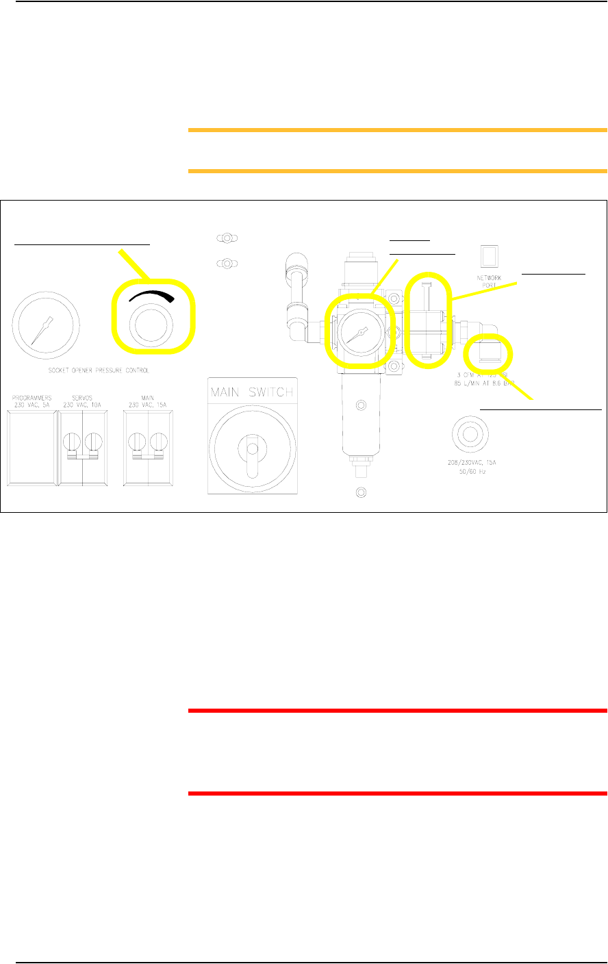
Figure 2-1—Pneumatic input and controls on the input panel
External Air Line Connection—
The low pressure air source is supplied to the system through the external air
line connected to the air filter. The PS288 air filter is a secondary filter only.
The main filter should be a 10 micron filter/regulator installed between the
factory compressor and the PS288. The external air line should be at least
3 meters (10 feet) long to allow the supplied air to cool sufficiently so that
water vapor contained in the air condenses and can be extracted. See Figure
2-1 for the location of the external air line connection.
CAUTION: Oil, excessive moisture, or poorly filtered air will
obstruct the system’s internal air network, affect performance, and
void the warranty related to air system failure. If oil or excessive
moisture is detected, call Data I/O Customer Support immediately.
Main Air Pressure Gauge—
The main air pressure gauge displays the air pressure the PS288 uses inter-
nally to generate vacuum and air operations. The main pressure regulator is
pre-set to 586 kiloPascals (85 PSI) as read on the gauge on the input panel.
This setting is not adjustable. See Figure 2-1 for the location of the main air
pressure gauge.
Main air
pressure gauge
Socket opener pressure control
External air line connection
Main air valve
Set Up • Making the Necessary Connections
PS288 Owner’s Manual 2—3
Socket Opener Pressure Control—
NOTE: The Socket Actuator must be switched on from the AH500
software before the regulator gauge will display a reading.
The socket opener pressure control, also on the input panel, controls the air
pressure used to lower the Socket Actuator that opens the socket(s). This
pressure should remain in the range of 138-276 kiloPascals (20–40 PSI) but
may be adjusted within that range depending on the socket in use. See Fig-
ure 2-1 for the location of the socket opener pressure control.
NOTE: See “Adjusting the Socket Actuator Air Pressure” on page
5-37 for more information.
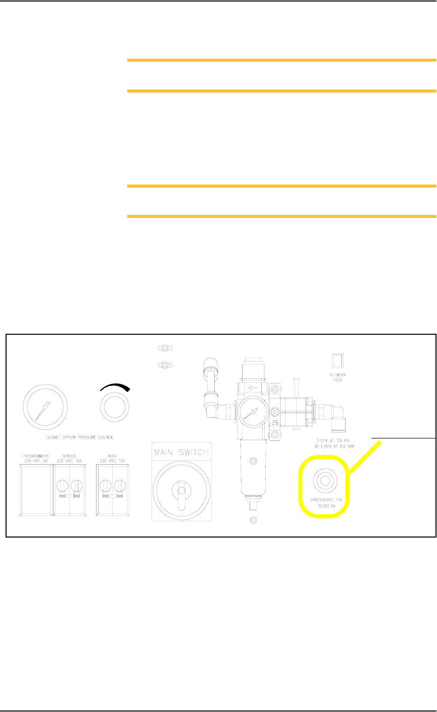
Electrical Input
Required power is provided through a customer-supplied 3 wire power cable
with one end terminated in an electrical plug as required by the customer’s
facility. Data I/O trained personnel route the other end of the 3 wire power
cable through the input panel and screw it into a terminal block inside the
PS288. See Figure 2-2 for the power cable routing through the input panel.
.
Figure 2-2—Power cable routing through input panel
Power cable routing